- 您现在的位置:买卖IC网 > PDF目录370133 > 7549 (Renesas Technology Corp.) SINGLE-CHIP 8-BIT CMOS MICROCOMPUTER PDF资料下载
参数资料
| 型号: | 7549 |
| 厂商: | Renesas Technology Corp. |
| 英文描述: | SINGLE-CHIP 8-BIT CMOS MICROCOMPUTER |
| 中文描述: | 单芯片8位CMOS微机 |
| 文件页数: | 45/73页 |
| 文件大小: | 1272K |
| 代理商: | 7549 |
第1页第2页第3页第4页第5页第6页第7页第8页第9页第10页第11页第12页第13页第14页第15页第16页第17页第18页第19页第20页第21页第22页第23页第24页第25页第26页第27页第28页第29页第30页第31页第32页第33页第34页第35页第36页第37页第38页第39页第40页第41页第42页第43页第44页当前第45页第46页第47页第48页第49页第50页第51页第52页第53页第54页第55页第56页第57页第58页第59页第60页第61页第62页第63页第64页第65页第66页第67页第68页第69页第70页第71页第72页第73页
Rev.2.00
REJ03B0202-0200
Mar 05, 2007
Page 45 of 70
7549 Group
PRELIMINARY
Notice: This is not a final specification.
Some parametric limits are subject to change.
Oscillation Control
Clock mode register
Clock mode register contains the oscillation control bits of each
oscillation circuits, clock selection bits and etc
Clock selection bits
φ
SOURCE can be selected by the clock selection bits (bits 5 and
4 in clock mode register).
φ
SOURCE can be selected from low-
speed on-chip oscillator, high-speed on-chip oscillator, X
IN
/X
CIN
oscillaton or external clock input by the clock selection bits.
φ
SOURCE is also used to the clock for peripheral functions.
When the oscillation method selection bits (bits 1 and 0 in
FSROM1) is set to “00
2
” (oscillation pins not used), setting the
clock selection bits to “10
2
” (X
IN
/X
CIN
oscillation, external
clock input) is disabled.
Clock division ratio selection bit
The internal clock
φ
is generated by dividing
φ
SOURCE.
Select the division ratio using the clock division ration selection
bits (bits 7 and 6 in CLKM).
The division ratio can be selected from among
φ
SOURCE/8
(low-speed mode), /4 (middle-speed mode), /2 (high-speed
mode), and no division (double-speed mode).
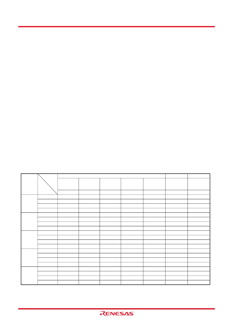
Table 9 shows the division ratio (mode) settings.
When releasing reset, the low-speed on-chip oscillator is selected
as
φ
SOURCE, and
φ
SOURCE/8 is selected as the internal clock.
The high-speed on-chip oscillator is stopped at this time. If an
oscillation circuit is connected to the clock pin, oscillation starts.
To switch
φ
SOURCE to X
IN
/X
CIN
oscillation, generate wait time
using the on-chip oscillator until the oscillation is stabilized.
: can be “0” or “1”, no change in outcome
Table 9
Setting the clock division (mode)
φ
SOURCE
CLKM
Clock division
ratio selection
bits
Bit 7, 6
11
10
01
00
11
10
01
00
11
10
01
00
11
10
01
00
11
10
01
00
FSROM1
Oscillation
method
selection bits
Bit 1, 0
01
01
01
01
10
10
10
10
11
11
11
11
FSROM2
Low-speed on-
chip oscillator
control bit
Bit 4
1/0
1/0
1/0
1/0
Clock
selection bits
X
IN
/XC
IN
oscillation
control bit
Bit 2
0
0
0
0
0
0
0
0
High-speed on-chip
oscillator oscillation
control bit
Bit 1
0
0
0
0
Low-speed on-chip
oscillator oscillation
control bit
Bit 0
0
0
0
0
Bit 5, 4
10
10
10
10
10
10
10
10
10
10
10
10
01
01
01
01
00
00
00
00
X
IN
Double-speed
High-speed
Middle-speed
Low-speed
Double-speed
High-speed
Middle-speed
Low-speed
Double-speed
High-speed
Middle-speed
Low-speed
Double-speed
High-speed
Middle-speed
Low-speed
Double-speed
High-speed
Middle-speed
Low-speed
X
CIN
External
clock
High-speed
on-chip
oscillator
Low-speed
on-chip
oscillator
bit
Mode
相关PDF资料 |
PDF描述 |
|---|---|
| 75HQ | SCHOTTKY RECTIFIER |
| 75HQ030 | SCHOTTKY RECTIFIER |
| 75HQ035 | SCHOTTKY RECTIFIER |
| 75HQ040 | SCHOTTKY RECTIFIER |
| 75HQ045 | SCHOTTKY RECTIFIER |
相关代理商/技术参数 |
参数描述 |
|---|---|
| 7549_0710 | 制造商:RENESAS 制造商全称:Renesas Technology Corp 功能描述:SINGLE-CHIP 8-BIT CMOS MICROCOMPUTER |
| 7549_09 | 制造商:RENESAS 制造商全称:Renesas Technology Corp 功能描述:SINGLE-CHIP 8-BIT CMOS MICROCOMPUTER |
| 7-5-4905 | 功能描述:3M 4905 VHB TAPE SPECIALTY TAPES 制造商:3m (tc) 系列:VHB?? 4905 零件状态:在售 厚度 - 粘合剂:- 厚度 - 底布,载体:- 标准包装:1 |
| 754905-1 | 功能描述:PIN ATT/ROLL AUTO IV 制造商:te connectivity amp connectors 系列:* 零件状态:有效 标准包装:1 |
| 7-5-4910 | 功能描述:3M 4910 VHB TAPE SPECIALTY TAPES 制造商:3m (tc) 系列:VHB?? 4910 零件状态:在售 底布,载体:丙烯酸泡棉 厚度 - 粘合剂:- 厚度 - 底布,载体:- 标准包装:1 |
发布紧急采购,3分钟左右您将得到回复。