参数资料
| 型号: | ADE7116ASTZF8 |
| 厂商: | Analog Devices Inc |
| 文件页数: | 115/152页 |
| 文件大小: | 0K |
| 描述: | IC ENERGY METER 64-LQFP |
| 产品变化通告: | Product Discontinuance 27/Oct/2011 |
| 标准包装: | 160 |
| 输入阻抗: | 770 千欧 |
| 测量误差: | 0.1% |
| 电压 - 高输入/输出: | 2V |
| 电压 - 低输入/输出: | 0.8V |
| 电流 - 电源: | 4mA |
| 电源电压: | 2.4 V ~ 3.7 V |
| 测量仪表类型: | 单相 |
| 工作温度: | -40°C ~ 85°C |
| 安装类型: | 表面贴装 |
| 封装/外壳: | 64-LQFP |
| 供应商设备封装: | 64-LQFP(10x10) |
| 包装: | 托盘 |
第1页第2页第3页第4页第5页第6页第7页第8页第9页第10页第11页第12页第13页第14页第15页第16页第17页第18页第19页第20页第21页第22页第23页第24页第25页第26页第27页第28页第29页第30页第31页第32页第33页第34页第35页第36页第37页第38页第39页第40页第41页第42页第43页第44页第45页第46页第47页第48页第49页第50页第51页第52页第53页第54页第55页第56页第57页第58页第59页第60页第61页第62页第63页第64页第65页第66页第67页第68页第69页第70页第71页第72页第73页第74页第75页第76页第77页第78页第79页第80页第81页第82页第83页第84页第85页第86页第87页第88页第89页第90页第91页第92页第93页第94页第95页第96页第97页第98页第99页第100页第101页第102页第103页第104页第105页第106页第107页第108页第109页第110页第111页第112页第113页第114页当前第115页第116页第117页第118页第119页第120页第121页第122页第123页第124页第125页第126页第127页第128页第129页第130页第131页第132页第133页第134页第135页第136页第137页第138页第139页第140页第141页第142页第143页第144页第145页第146页第147页第148页第149页第150页第151页第152页
�� ��
��
��ADE7116/ADE7156/ADE7166/ADE7169/ADE7566/ADE7569�
�TIMERS�
�Each� ADE7116/ADE7156/ADE7166/ADE7169/ADE7566/�
�ADE7569� has� three� 16-bit� timer/counters:� Timer/Counter� 0,�
�Timer/Counter� 1,� and� Timer/Counter� 2.� The� timer/counter�
�hardware� is� included� on-chip� to� relieve� the� processor� core� of�
�overhead� inherent� in� implementing� timer/counter� functionality�
�in� software.� Each� timer/counter� consists� of� two� 8-bit� registers:�
�THx� and� TLx� (x� =� 0,� 1,� or� 2).� All� three� timers� can� be� configured�
�to� operate� as� timers� or� as� event� counters.�
�When� functioning� as� a� timer,� the� TLx� SFR� is� incremented� every�
�machine� cycle.� (Users� can� think� of� it� as� counting� machine� cycles.)�
�Because� a� machine� cycle� on� a� single-cycle� core� consists� of� one� core�
�clock� period,� the� maximum� count� rate� is� the� core� clock� frequency.�
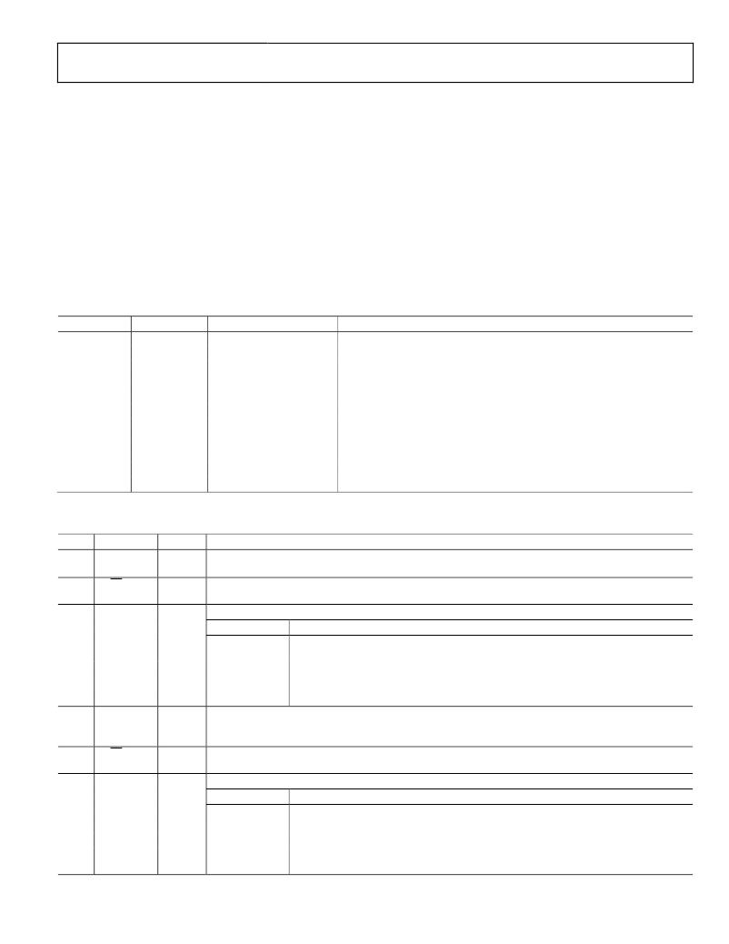
�Table� 112.� Timer� SFRs�
�When� functioning� as� a� counter,� the� TLx� register� is� incremented�
�by� a� 1-to-0� transition� at� its� corresponding� external� input� pin:�
�T0,� T1,� or� T2.� When� the� samples� show� a� high� in� one� cycle� and� a�
�low� in� the� next� cycle,� the� count� is� incremented.� Because� it� takes�
�two� machine� cycles� (two� core� clock� periods)� to� recognize� a� 1-to-0�
�transition,� the� maximum� count� rate� is� half� the� core� clock� frequency.�
�There� are� no� restrictions� on� the� duty� cycle� of� the� external� input�
�signal,� but� to� ensure� that� a� given� level� is� sampled� at� least� once�
�before� it� changes,� it� must� be� held� for� a� minimum� of� one� full�
�machine� cycle.� User� configuration� and� control� of� all� timer�
�operating� modes� is� achieved� via� the� SFRs� listed� in� Table� 112.�
�SFR�
�TCON�
�TMOD�
�TL0�
�TL1�
�TH0�
�TH1�
�T2CON�
�RCAP2L�
�RCAP2H�
�TL2�
�TH2�
�Address�
�0x88�
�0x89�
�0x8A�
�0x8B�
�0x8C�
�0x8D�
�0xC8�
�0xCA�
�0xCB�
�0xCC�
�0xCD�
�Bit� Addressable�
�Yes�
�No�
�No�
�No�
�No�
�No�
�Yes�
�No�
�No�
�No�
�No�
�Description�
�Timer/Counter� 0� and� Timer/Counter� 1� control� (see� Table� 114).�
�Timer/Counter� 0� and� Timer./Counter� 1� mode� (see� Table� 113).�
�Timer� 0� low� byte� (see� Table� 117).�
�Timer� 1� low� byte� (see� Table� 119).�
�Timer� 0� high� byte� (see� Table� 116).�
�Timer� 1� high� byte� (see� Table� 118).�
�Timer/Counter� 2� control� (see� Table� 115).�
�Timer� 2� reload/capture� low� byte� (see� Table� 123).�
�Timer� 2� reload/capture� high� byte� (see� Table� 122).�
�Timer� 2� low� byte� (Table� 121).�
�Timer� 2� high� byte� (see� Table� 120).�
�TIMER� REGISTERS�
�Table� 113.� Timer/Counter� 0� and� Timer/Counter� 1� Mode� SFR� (TMOD,� Address� 0x89)�
�Bit�
�7�
�Mnemonic�
�Gate1�
�Default�
�0�
�Description�
�Timer� 1� gating� control.� Set� by� software� to� enable� Timer/Counter� 1� only� when� the� INT1� pin� is� high� and� the�
�TR1� control� is� set.� Cleared� by� software� to� enable� Timer� 1� whenever� the� TR1� control� bit� is� set.�
�6�
�C/T1�
�0�
�Timer� 1� timer� or� counter� select� bit.� Set� by� software� to� select� counter� operation� (input� from� T1� pin).� Cleared�
�by� software� to� select� the� timer� operation� (input� from� internal� system� clock).�
�[5:4]�
�T1/M1,�
�T1/M0�
�00�
�Timer� 1� mode� select� bits.�
�T1/M1,� T1/M0�
�Result�
�00�
�TH1� (Address� 0x8D)� operates� as� an� 8-bit� timer/counter.� TL1� (Address� 0x8D)� serves� as�
�5-bit� prescaler.�
�01�
�10�
�11�
�16-bit� timer/counter.� TH1� and� TL1� are� cascaded;� there� is� no� prescaler.�
�8-bit� autoreload� timer/counter.� TH1� holds� a� value� to� reload� into� TL1� each� time� it� overflows.�
�Timer/Counter� 1� stopped.�
�3�
�Gate0�
�0�
�Timer� 0� gating� control.� Set� by� software� to� enable� Timer/Counter� 0� only� when� the� INT0� pin� is� high� and� the� TR0�
�control� bit� is� set.� Cleared� by� software� to� enable� Timer� 0� whenever� the� TR0� control� bit� is� set� in� the�
�Timer/Counter� 0� and� Timer/Counter� 1� control� SFR� (TCON,� Address� 0x88)�
�2�
�C/T0�
�0�
�Timer� 0� timer� or� counter� select� bit.� Set� by� software� to� the� select� counter� operation� (input� from� T0� pin).�
�Cleared� by� software� to� the� select� timer� operation� (input� from� internal� system� clock).�
�[1:0]�
�T0/M1,�
�T0/M0�
�00�
�Timer� 0� mode� select� bits.�
�T0/M1,� T0/M0�
�Result�
�00�
�TH0� operates� as� an� 8-bit� timer/counter.� TL0� serves� as� a� 5-bit� prescaler.�
�01�
�16-bit� timer/counter.� TH0� and� TL0� are� cascaded;� there� is� no� prescaler.�
�10�
�8-bit� autoreload� timer/counter.� TH0� holds� a� value� to� reload� into� TL0� each� time� it� overflows.�
�11�
�TL0� is� an� 8-bit� timer/counter� controlled� by� the� standard� Timer� 0� control� bits.� TH0� is� an�
�8-bit� timer� only,� controlled� by� Timer� 1� control� bits.�
�Rev.� B� |� Page� 115� of� 1� 52�
�相关PDF资料 |
PDF描述 |
|---|---|
| ADE5166ASTZF62-RL | IC METER/8052/RTC/LCD DRV 64LQFP |
| ADE5166ASTZF62 | IC METER/8052/RTC/LCD DRV 64LQFP |
| NCP699SN28T1G | IC REG LDO 2.8V 240MA 5TSOP |
| RSC50DRYN-S13 | CONN EDGECARD 100POS .100 EXTEND |
| LFEC3E-4QN208I | IC FPGA 3.1KLUTS 208PQFP |
相关代理商/技术参数 |
参数描述 |
|---|---|
| ADE7116ASTZF8-RL | 功能描述:IC ENERGY METER 64-LQFP RoHS:是 类别:集成电路 (IC) >> PMIC - 能量测量 系列:- 产品培训模块:Lead (SnPb) Finish for COTS Obsolescence Mitigation Program 标准包装:2,500 系列:* |
| ADE7156ASTZF16 | 功能描述:IC ENERGY METER 64-LQFP RoHS:是 类别:集成电路 (IC) >> PMIC - 能量测量 系列:- 产品培训模块:Lead (SnPb) Finish for COTS Obsolescence Mitigation Program 标准包装:2,500 系列:* |
| ADE7156ASTZF16-RL | 功能描述:IC ENERGY METER 64-LQFP RoHS:是 类别:集成电路 (IC) >> PMIC - 能量测量 系列:- 产品培训模块:Lead (SnPb) Finish for COTS Obsolescence Mitigation Program 标准包装:2,500 系列:* |
| ADE7156ASTZF8 | 功能描述:IC ENERGY METER 64-LQFP RoHS:是 类别:集成电路 (IC) >> PMIC - 能量测量 系列:- 产品培训模块:Lead (SnPb) Finish for COTS Obsolescence Mitigation Program 标准包装:2,500 系列:* |
| ADE7156ASTZF8-RL | 功能描述:IC ENERGY METER 64-LQFP RoHS:是 类别:集成电路 (IC) >> PMIC - 能量测量 系列:- 产品培训模块:Lead (SnPb) Finish for COTS Obsolescence Mitigation Program 标准包装:2,500 系列:* |
发布紧急采购,3分钟左右您将得到回复。