参数资料
| 型号: | ADE7116ASTZF8 |
| 厂商: | Analog Devices Inc |
| 文件页数: | 59/152页 |
| 文件大小: | 0K |
| 描述: | IC ENERGY METER 64-LQFP |
| 产品变化通告: | Product Discontinuance 27/Oct/2011 |
| 标准包装: | 160 |
| 输入阻抗: | 770 千欧 |
| 测量误差: | 0.1% |
| 电压 - 高输入/输出: | 2V |
| 电压 - 低输入/输出: | 0.8V |
| 电流 - 电源: | 4mA |
| 电源电压: | 2.4 V ~ 3.7 V |
| 测量仪表类型: | 单相 |
| 工作温度: | -40°C ~ 85°C |
| 安装类型: | 表面贴装 |
| 封装/外壳: | 64-LQFP |
| 供应商设备封装: | 64-LQFP(10x10) |
| 包装: | 托盘 |
第1页第2页第3页第4页第5页第6页第7页第8页第9页第10页第11页第12页第13页第14页第15页第16页第17页第18页第19页第20页第21页第22页第23页第24页第25页第26页第27页第28页第29页第30页第31页第32页第33页第34页第35页第36页第37页第38页第39页第40页第41页第42页第43页第44页第45页第46页第47页第48页第49页第50页第51页第52页第53页第54页第55页第56页第57页第58页当前第59页第60页第61页第62页第63页第64页第65页第66页第67页第68页第69页第70页第71页第72页第73页第74页第75页第76页第77页第78页第79页第80页第81页第82页第83页第84页第85页第86页第87页第88页第89页第90页第91页第92页第93页第94页第95页第96页第97页第98页第99页第100页第101页第102页第103页第104页第105页第106页第107页第108页第109页第110页第111页第112页第113页第114页第115页第116页第117页第118页第119页第120页第121页第122页第123页第124页第125页第126页第127页第128页第129页第130页第131页第132页第133页第134页第135页第136页第137页第138页第139页第140页第141页第142页第143页第144页第145页第146页第147页第148页第149页第150页第151页第152页
�� �
�
�ADE7116/ADE7156/ADE7166/ADE7169/ADE7566/ADE7569�
�PHASE� COMPENSATION�
�The� ADE7116/ADE7156/ADE7166/ADE7169/ADE7566/�
�ADE7569� must� work� with� transducers� that� can� have� inherent�
�RMS� CALCULATION�
�The� root� mean� square� (rms)� value� of� a� continuous� signal� V(t)� is�
�defined� as�
�∫�
�phase� errors.� For� example,� a� phase� error� of� 0.1°� to� 0.3°� is� not�
�uncommon� for� a� current� transformer� (CT).� These� phase� errors�
�can� vary� from� part� to� part,� and� they� must� be� corrected� to� perform�
�accurate� power� calculations.� The� errors� associated� with� phase�
�V� rms� =�
�1�
�T�
�T�
�� V� 2� (� t� )� dt�
�0�
�(3)�
�mismatch� are� particularly� noticeable� at� low� power� factors.� The�
�ADE7116/ADE7156/ADE7166/ADE7169/ADE7566/ADE7569�
�provide� a� means� of� digitally� calibrating� these� small� phase� errors.�
�The� part� allows� a� small� time� delay� or� time� advance� to� be� intro-�
�duced� into� the� signal� processing� chain� to� compensate� for� small�
�phase� errors.� Because� the� compensation� is� in� time,� this� technique�
�should� be� used� only� for� small� phase� errors� in� the� range� of� 0.1°�
�to� 0.5°.� Correcting� large� phase� errors� using� a� time� shift� technique�
�For� time� sampling� signals,� rms� calculation� involves� squaring� the�
�signal,� taking� the� average,� and� obtaining� the� square� root.� The�
�ADE7116/ADE7156/ADE7166/ADE7169/ADE7566/ADE7569�
�implement� this� method� by� serially� squaring� the� inputs,� averaging�
�them,� and� then� taking� the� square� root� of� the� average.� The� averaging�
�part� of� this� signal� processing� is� done� by� implementing� a� low-pass�
�filter� (LPF3� in� Figure� 60,� Figure� 62,� and� Figure� 63).� This� LPF�
�has� a� ?3� dB� cutoff� frequency� of� 2� Hz� when� MCLK� =� 4.096� MHz.�
�can� introduce� significant� phase� errors� at� higher� harmonics.�
�The� phase� calibration� register� (PHCAL[7:0],� Address� 0x10)� is� a�
�twos� complement,� signed,� single-byte� register� that� has� values�
�ranging� from� 0x82� (?126d)� to� 0x68� (+104d).�
�V� (� t� )� =� 2� ×� V� sin(� ω� t� )�
�where� V� is� the� rms� voltage.�
�V� 2� (� t� )� =� V� 2� ?� V� 2� cos� (� 2� ω� t� )�
�(4)�
�(5)�
�The� PHCAL� register� is� centered� at� 0x40,� meaning� that� writing�
�0x40� to� the� register� gives� 0� delay.� By� changing� this� register,� the�
�time� delay� in� the� voltage� channel� signal� path� can� change� from�
�?231.93� μs� to� +48.83� μs� (MCLK� =� 4.096� MHz).� One� LSB� is�
�equivalent� to� a� 1.22� μs� (4.096� MHz/5)� time� delay� or� advance.�
�A� line� frequency� of� 60� Hz� gives� a� phase� resolution� of� 0.026°� at�
�the� fundamental� (that� is,� 360°� ×� 1.22� μs� ×� 60� Hz).�
�When� this� signal� goes� through� LPF3,� the� cos(2ωt)� term� is� attenu-�
�ated� and� only� the� dc� term,� V� rms2� (shown� as� V� 2� in� Figure� 60)� goes�
�through.�
�V� 2� (� t� )� =� V� 2� –� V� 2� cos� (2� ω� t� )�
�V� (� t� )� =� √� 2� ×� V� sin(� ω� t� )�
�LPF3�
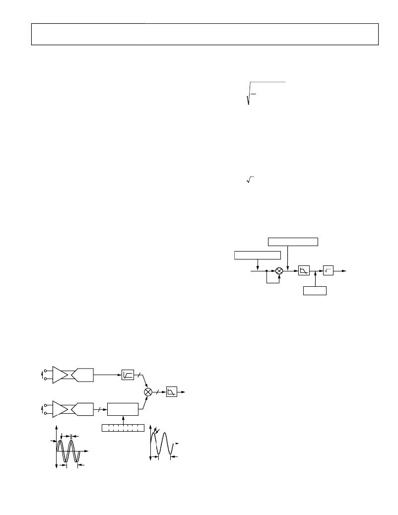
�Figure� 59� illustrates� how� the� phase� compensation� is� used� to�
�remove� a� 0.1°� phase� lead� in� the� current� channel� due� to� the�
�INPUT�
�V�
�external� transducer.� To� cancel� the� lead� (0.1°)� in� the� current�
�channel,� a� phase� lead� must� also� be� introduced� into� the� voltage�
�channel.� The� resolution� of� the� phase� adjustment� allows� the�
�introduction� of� a� phase� lead� in� increments� of� 0.026°.� The� phase�
�lead� is� achieved� by� introducing� a� time� advance� into� the� voltage�
�channel.� A� time� advance� of� 4.88� μs� is� made� by� writing� ?4� (0x3C)�
�to� the� time� delay� block,� thus� reducing� the� amount� of� time� delay�
�by� 4.88� μs� or,� equivalently,� a� phase� lead� of� approximately� 0.1°� at� a�
�line� frequency� of� 60� Hz� (0x3C� represents� ?4� because� the� register� is�
�centered� with� 0� at� 0x40).�
�V� 2� (� t� )� =� V� 2�
�Figure� 60.� RMS� Signal� Processing�
�The� I� rms� signal� can� be� read� from� the� waveform� register� by� setting�
�the� WAVMODE� register� (Address� 0x0D)� and� setting� the� WFSM�
�bit� (Bit� 5)� in� the� Interrupt� Enable� 3� SFR� (MIRQENH,� Address�
�0xDB).� Like� the� current� and� voltage� channel� waveform� sampling�
�modes,� the� waveform� data� is� available� at� sample� rates� of�
�25.6� kSPS,� 12.8� kSPS,� 6.4� kSPS,� and� 3.2� kSPS.�
�It� is� important� to� note� that� when� the� current� input� is� larger� than�
�I� PA�
�HPF�
�24�
�40%� of� full� scale,� the� I� rms� waveform� sample� register� does� not�
�I�
�PGA1�
�ADC� 1�
�represent� the� true� processed� rms� value.� The� rms� value� processed�
�I� N�
�24�
�LPF2�
�with� this� level� of� input� is� larger� than� the� 24-bit� read� by� the� wave-�
�form� register,� making� the� value� read� truncated� on� the� high� end.�
�V�
�V� P�
�V� N�
�PGA2�
�ADC� 2�
�1�
�7�
�DELAY� BLOCK�
�1.22μs/LSB�
�0�
�CHANNEL� 2� DELAY�
�REDUCED� BY� 4.88μs�
�(0.1°LEAD� AT� 60Hz)�
�0x0B� IN� PHCAL[7:0]�
�V�
�Current� Channel� RMS� Calculation�
�Each� ADE7116/ADE7156/ADE7166/ADE7169/ADE7566/�
�ADE7569� simultaneously� calculates� the� rms� values� for� the� current�
�V�
�1� 0� 0� 1� 0� 1� 1� 1�
�I�
�and� voltage� channels� in� different� registers.� Figure� 61� and� Figure� 62�
�I�
�60Hz�
�0.1°�
�PHCAL[7:0]�
�–231.93μs� TO� +48.83μs�
�60Hz�
�show� the� details� of� the� signal� processing� chain� for� the� rms�
�calculation� on� the� current� channel.� The� current� channel� rms�
�value� is� processed� from� the� samples� used� in� the� current� channel�
�waveform� sampling� mode� and� is� stored� in� an� unsigned� 24-bit�
�register� (I� rms� ).� One� LSB� of� the� current� channel� rms� register� is�
�Figure� 59.� Phase� Calibration�
�equivalent� to� 1� LSB� of� a� current� channel� waveform� sample.�
�Rev.� B� |� Page� 59� of� 1� 5� 2�
�相关PDF资料 |
PDF描述 |
|---|---|
| ADE5166ASTZF62-RL | IC METER/8052/RTC/LCD DRV 64LQFP |
| ADE5166ASTZF62 | IC METER/8052/RTC/LCD DRV 64LQFP |
| NCP699SN28T1G | IC REG LDO 2.8V 240MA 5TSOP |
| RSC50DRYN-S13 | CONN EDGECARD 100POS .100 EXTEND |
| LFEC3E-4QN208I | IC FPGA 3.1KLUTS 208PQFP |
相关代理商/技术参数 |
参数描述 |
|---|---|
| ADE7116ASTZF8-RL | 功能描述:IC ENERGY METER 64-LQFP RoHS:是 类别:集成电路 (IC) >> PMIC - 能量测量 系列:- 产品培训模块:Lead (SnPb) Finish for COTS Obsolescence Mitigation Program 标准包装:2,500 系列:* |
| ADE7156ASTZF16 | 功能描述:IC ENERGY METER 64-LQFP RoHS:是 类别:集成电路 (IC) >> PMIC - 能量测量 系列:- 产品培训模块:Lead (SnPb) Finish for COTS Obsolescence Mitigation Program 标准包装:2,500 系列:* |
| ADE7156ASTZF16-RL | 功能描述:IC ENERGY METER 64-LQFP RoHS:是 类别:集成电路 (IC) >> PMIC - 能量测量 系列:- 产品培训模块:Lead (SnPb) Finish for COTS Obsolescence Mitigation Program 标准包装:2,500 系列:* |
| ADE7156ASTZF8 | 功能描述:IC ENERGY METER 64-LQFP RoHS:是 类别:集成电路 (IC) >> PMIC - 能量测量 系列:- 产品培训模块:Lead (SnPb) Finish for COTS Obsolescence Mitigation Program 标准包装:2,500 系列:* |
| ADE7156ASTZF8-RL | 功能描述:IC ENERGY METER 64-LQFP RoHS:是 类别:集成电路 (IC) >> PMIC - 能量测量 系列:- 产品培训模块:Lead (SnPb) Finish for COTS Obsolescence Mitigation Program 标准包装:2,500 系列:* |
发布紧急采购,3分钟左右您将得到回复。