- 您现在的位置:买卖IC网 > PDF目录175506 > I5104XY (WINBOND ELECTRONICS CORP) 262.2 SEC, SPEECH SYNTHESIZER WITH RCDG, UUC25 PDF资料下载
参数资料
| 型号: | I5104XY |
| 厂商: | WINBOND ELECTRONICS CORP |
| 元件分类: | 音频合成 |
| 英文描述: | 262.2 SEC, SPEECH SYNTHESIZER WITH RCDG, UUC25 |
| 封装: | DIE-25 |
| 文件页数: | 86/87页 |
| 文件大小: | 616K |
| 代理商: | I5104XY |
第1页第2页第3页第4页第5页第6页第7页第8页第9页第10页第11页第12页第13页第14页第15页第16页第17页第18页第19页第20页第21页第22页第23页第24页第25页第26页第27页第28页第29页第30页第31页第32页第33页第34页第35页第36页第37页第38页第39页第40页第41页第42页第43页第44页第45页第46页第47页第48页第49页第50页第51页第52页第53页第54页第55页第56页第57页第58页第59页第60页第61页第62页第63页第64页第65页第66页第67页第68页第69页第70页第71页第72页第73页第74页第75页第76页第77页第78页第79页第80页第81页第82页第83页第84页第85页当前第86页第87页
88
8393B-MCU Wireless-02/13
ATmega256/128/64RFR2
necessary for a robust oscillation during stable operation. This also keeps the drive
level of the crystal low.
Crystals with a higher load capacitance are generally less sensitive to parasitic pulling
effects caused by variations of external components or board and circuit parasitics. On
the other hand a larger crystal load capacitance results in a longer start-up time and a
higher steady state current consumption.
9.6.5.3 External Reference Frequency Setup
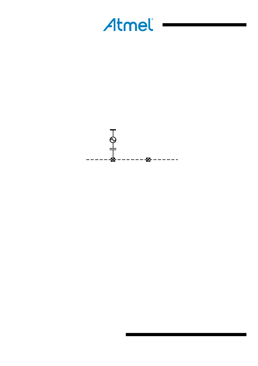
When using an external reference frequency, the signal must be connected to
pin XTAL1 as indicated in Figure 9-27 below and the bits XTAL_MODE of register
XOSC_CTRL need to be set to the external oscillator mode. The oscillation peak-to-
peak amplitude shall between 100 mV and 500 mV, the optimum range is between
400 mV and 500 mV. Pin XTAL2 should not be wired
Figure 9-27. Setup for Using an External Frequency Reference
XTAL2
XTAL1
IC internal
PCB
16 MHz
9.6.6 Frequency Synthesizer (PLL)
The main features of the phase-locked loop are:
Generate RX/TX frequencies for all 2.4 GHz channels of IEEE 802.15.4;
Autonomous calibration loops for stable operation within the operating range;
Two PLL-interrupts for status indication;
Fast PLL settling to support frequency hopping;
9.6.6.1 Overview
The PLL generates the RF frequencies for the radio transceiver. During receive
operation the frequency synthesizer works as a local oscillator for the receive frequency
of the radio transceiver. During transmit operation the voltage-controlled oscillator
(VCO) is directly modulated to generate the RF transmit signal. The frequency
synthesizer is implemented as a fractional-N PLL.
Two calibration loops ensure correct PLL functionality within the specified operating
limits.
9.6.6.2 Frequency Agility
When the PLL is enabled during state transition from TRX_OFF to PLL_ON the settling
time is typically tTR4 = 110 s including the settling time of the analog voltage regulator
(AVREG) and the PLL self calibration (refer to Table 9-9 on page 46Table 9-9). A lock
of the PLL is indicated with a TRX24_PLL_LOCK interrupt.
Switching between 2.4 GHz ISM band channels in PLL_ON or RX_ON states is
typically done within tTR20 = 11 s. This makes the radio transceiver highly suitable for
frequency hopping applications.
相关PDF资料 |
PDF描述 |
|---|---|
| IA3-1206WA00D5 | 0 MHz - 18000 MHz RF/MICROWAVE FIXED ATTENUATOR |
| IA3-0706SS58D0 | 0 MHz - 18000 MHz RF/MICROWAVE FIXED ATTENUATOR |
| IA3-2010SG30D0 | 0 MHz - 18000 MHz RF/MICROWAVE FIXED ATTENUATOR |
| IAC-0706SG04D0 | 0 MHz - 18000 MHz RF/MICROWAVE FIXED ATTENUATOR |
| IAC-0706SS22D0 | 0 MHz - 18000 MHz RF/MICROWAVE FIXED ATTENUATOR |
相关代理商/技术参数 |
参数描述 |
|---|---|
| I5108E | 制造商:WINBOND 制造商全称:Winbond 功能描述:SINGLE-CHIP 1 TO 16 MINUTES DURATION VOICE RECORD/PLAYBACK DEVICES WITH DIGITAL STORAGE CAPABILITY |
| I5108EI | 制造商:WINBOND 制造商全称:Winbond 功能描述:SINGLE-CHIP 1 TO 16 MINUTES DURATION VOICE RECORD/PLAYBACK DEVICES WITH DIGITAL STORAGE CAPABILITY |
| I5108S | 制造商:WINBOND 制造商全称:Winbond 功能描述:SINGLE-CHIP 1 TO 16 MINUTES DURATION VOICE RECORD/PLAYBACK DEVICES WITH DIGITAL STORAGE CAPABILITY |
| I5108SI | 制造商:WINBOND 制造商全称:Winbond 功能描述:SINGLE-CHIP 1 TO 16 MINUTES DURATION VOICE RECORD/PLAYBACK DEVICES WITH DIGITAL STORAGE CAPABILITY |
| I5108X | 制造商:WINBOND 制造商全称:Winbond 功能描述:SINGLE-CHIP 1 TO 16 MINUTES DURATION VOICE RECORD/PLAYBACK DEVICES WITH DIGITAL STORAGE CAPABILITY |
发布紧急采购,3分钟左右您将得到回复。