- 您现在的位置:买卖IC网 > PDF目录98143 > ST52510F3M6 (STMICROELECTRONICS) MICROCONTROLLER, PDSO20 PDF资料下载
参数资料
| 型号: | ST52510F3M6 |
| 厂商: | STMICROELECTRONICS |
| 元件分类: | 微控制器/微处理器 |
| 英文描述: | MICROCONTROLLER, PDSO20 |
| 封装: | SOP-20 |
| 文件页数: | 111/136页 |
| 文件大小: | 3335K |
| 代理商: | ST52510F3M6 |
第1页第2页第3页第4页第5页第6页第7页第8页第9页第10页第11页第12页第13页第14页第15页第16页第17页第18页第19页第20页第21页第22页第23页第24页第25页第26页第27页第28页第29页第30页第31页第32页第33页第34页第35页第36页第37页第38页第39页第40页第41页第42页第43页第44页第45页第46页第47页第48页第49页第50页第51页第52页第53页第54页第55页第56页第57页第58页第59页第60页第61页第62页第63页第64页第65页第66页第67页第68页第69页第70页第71页第72页第73页第74页第75页第76页第77页第78页第79页第80页第81页第82页第83页第84页第85页第86页第87页第88页第89页第90页第91页第92页第93页第94页第95页第96页第97页第98页第99页第100页第101页第102页第103页第104页第105页第106页第107页第108页第109页第110页当前第111页第112页第113页第114页第115页第116页第117页第118页第119页第120页第121页第122页第123页第124页第125页第126页第127页第128页第129页第130页第131页第132页第133页第134页第135页第136页
Obsolete
Product(s)
- Obsolete
Product(s)
When the Timers are in Reset status, or when the
device is reset, the TxOUT pins goes in threestate.
If these outputs are used to drive external devices,
it is recommended that the related pins be left in
the default configuration (Input threestate) or
change them in this configuration.
In PWM mode the PWM/Timers can only be Set or
Reset: Start/Stop signals do not affect the Timers.
TxRES resets the content of the 16-bit counter to
zero. It is generated by writing 0 in the
corresponding TxRES bit of the PWMx_CR1
Configuration Register and/or it can be driven by
the TRES pin if it is configured (only Timer0).
12.3.1 Simultaneous Start.
The PWM/Timers can be started simultaneously.
The T0SYNC and T1SYNC bits in PWM0_CR3
Configuration Registers mask the reset of each
timer. After enabling each single PWM/Timer, they
are started by putting off the mask with a single
writing in the PWM0_CR3 Register.
The timers start counting simultaneously, but the
output pulses are generated according to the
modality configured (square or pulse mode).
12.4 Timer Interrupts
The PWM/Timer can be programmed to generate
an Interrupt Request, both on the falling and the
rising of the TxOUT signal and when there’s a
STOP signal (external or internal).
By using the TxIES, TxIER and TxIEF bits of the
Configuration Registers PWMx_CR1, the interrupt
sources can be switched on/off. All the interrupt
sources may be activated at the same time:
sources can be distinguished by reading the
PWMx_STATUS Input Register.
The interrupt on the falling edge corresponds to
half of a counting period in Timer mode when the
waveform is set to Square Wave and to the end of
the Ton phase in PWM mode.
Note: when the PWM Counter is set to 0 or 65535,
the interrupt occurs at the end of each control
period.
In order to be active, the PWM/Timers interrupts
must be enabled by writing the Interrupt Mask
Register
(INT_MASK)
in
the
Configuration
Register Space, bits MSKT0 And MSKT1.
Note: Interrupt on TxOUT Rising Edge: the first
rising edge doesn’t give an interrupt.
12.5 PWM/Timer 0 Register Description
The following registers are related to the use of the
PWM/Timer 0.
12.5.1 PWM/Timer 0 Configuration Registers.
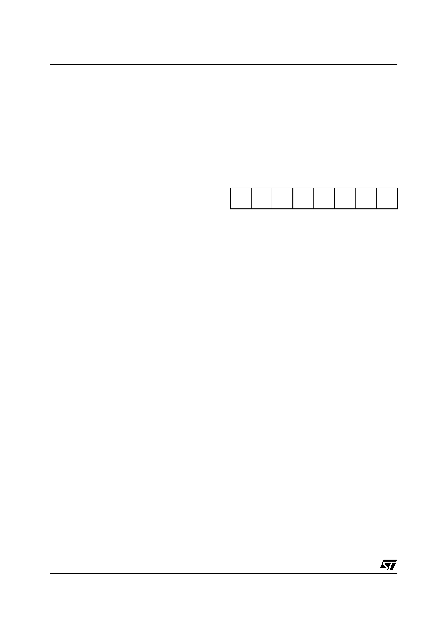
PWM/Timer 0 Control Register 1 (PWM0_CR1)
Configuration Register 9 (09h) Read/Write
Reset Value: 0000 0000 (00h)
Bit 7: T0MOD PWM/Timer 0 Mode
0: Timer Mode
1: PWM Mode
Bit 6: T0IES Interrupt on Stop signal Enable
0: interrupt disabled
1: interrupt enabled
Bit 5: T0IEF Interrupt on T0OUT falling Enable
0: interrupt disabled
1: interrupt enabled
Bit 4: T0IER Interrupt on T0OUT rising Enable
0: interrupt disabled
1: interrupt enabled
Bit 3: STRMOD Start signal mode
0: start/stop on level
1: start/stop on edge
Bit 2: T0STRT PWM/Timer 0 Start bit
0: Timer 0 stopped
1: Timer 0 started
Bit 1: RESMOD Reset signal mode
0: set/reset on level
1: set/reset on edge
Bit 0: T0RES PWM/Timer 0 Reset bit
0: PWM/Timer 0 reset
1: PWM/Timer 0 set
70
T0MOD
T0IES
T0IEF
T0IER STRMOD T0STRT RESMOD T0RES
相关PDF资料 |
PDF描述 |
|---|---|
| ST52E430B/D | 8-BIT, UVPROM, 20 MHz, MICROCONTROLLER, CDIP32 |
| ST52F510F1M6 | 8-BIT, FLASH, 24 MHz, MICROCONTROLLER, PDSO20 |
| ST52F510G0B6 | 8-BIT, FLASH, 24 MHz, MICROCONTROLLER, PDIP28 |
| ST52F513F0M6 | 8-BIT, FLASH, 24 MHz, MICROCONTROLLER, PDSO20 |
| ST52F513F1B6 | 8-BIT, FLASH, 24 MHz, MICROCONTROLLER, PDIP20 |
相关代理商/技术参数 |
参数描述 |
|---|---|
| ST52510G2 | 制造商:未知厂家 制造商全称:未知厂家 功能描述:8-BIT ICU WITH 10-BIT ADC. TWO TIMERS/PWM. I2C. SPI. SCI. UP TO 8K FLASH |
| ST52510G3 | 制造商:未知厂家 制造商全称:未知厂家 功能描述:8-BIT ICU WITH 10-BIT ADC. TWO TIMERS/PWM. I2C. SPI. SCI. UP TO 8K FLASH |
| ST52510K2 | 制造商:未知厂家 制造商全称:未知厂家 功能描述:8-BIT ICU WITH 10-BIT ADC. TWO TIMERS/PWM. I2C. SPI. SCI. UP TO 8K FLASH |
| ST52510K3 | 制造商:未知厂家 制造商全称:未知厂家 功能描述:8-BIT ICU WITH 10-BIT ADC. TWO TIMERS/PWM. I2C. SPI. SCI. UP TO 8K FLASH |
| ST52510Y2 | 制造商:未知厂家 制造商全称:未知厂家 功能描述:8-BIT ICU WITH 10-BIT ADC. TWO TIMERS/PWM. I2C. SPI. SCI. UP TO 8K FLASH |
发布紧急采购,3分钟左右您将得到回复。