- 您现在的位置:买卖IC网 > PDF目录98143 > ST52510F3M6 (STMICROELECTRONICS) MICROCONTROLLER, PDSO20 PDF资料下载
参数资料
| 型号: | ST52510F3M6 |
| 厂商: | STMICROELECTRONICS |
| 元件分类: | 微控制器/微处理器 |
| 英文描述: | MICROCONTROLLER, PDSO20 |
| 封装: | SOP-20 |
| 文件页数: | 131/136页 |
| 文件大小: | 3335K |
| 代理商: | ST52510F3M6 |
第1页第2页第3页第4页第5页第6页第7页第8页第9页第10页第11页第12页第13页第14页第15页第16页第17页第18页第19页第20页第21页第22页第23页第24页第25页第26页第27页第28页第29页第30页第31页第32页第33页第34页第35页第36页第37页第38页第39页第40页第41页第42页第43页第44页第45页第46页第47页第48页第49页第50页第51页第52页第53页第54页第55页第56页第57页第58页第59页第60页第61页第62页第63页第64页第65页第66页第67页第68页第69页第70页第71页第72页第73页第74页第75页第76页第77页第78页第79页第80页第81页第82页第83页第84页第85页第86页第87页第88页第89页第90页第91页第92页第93页第94页第95页第96页第97页第98页第99页第100页第101页第102页第103页第104页第105页第106页第107页第108页第109页第110页第111页第112页第113页第114页第115页第116页第117页第118页第119页第120页第121页第122页第123页第124页第125页第126页第127页第128页第129页第130页当前第131页第132页第133页第134页第135页第136页
Obsolete
Product(s)
- Obsolete
Product(s)
14.5 Register Description
In the following sections describe the registers
used by the I2C Interface are described.
14.5.1 I2C Interface Configuration Registers.
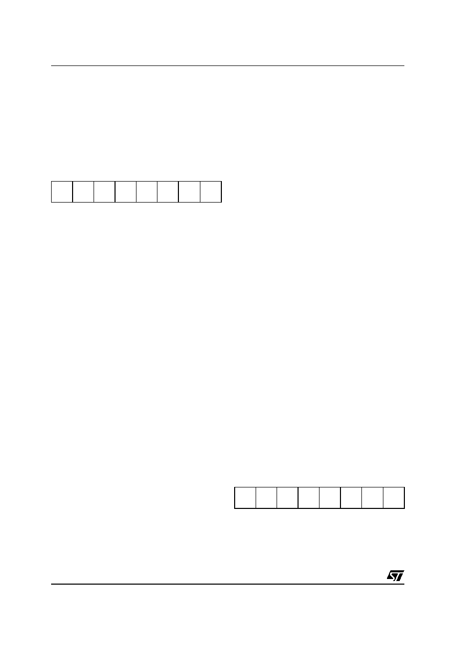
I2C Control Register (I2C_CR)
Configuration Register 16 (010h) Read/Write
Reset Value: 0000 0000 (00h)
Bit 7-6: Not Used. They must be held to 0.
Bit 5: PE Peripheral Enable.
This bit is set and cleared by software
0: peripheral disabled
1: peripheral enabled
Notes:
– When PE=0, all the bits of the I2C_CR register
and the SR register except the Stop bit are reset.
All outputs are released while PE=0
– When PE=1, the corresponding I/O pins are se-
lected by hardware as alternate functions.
– To enable the I2C interface, write the I2C_CR
register TWICE with PE=1 as the first write only
activates the interface (only PE is set).
Bit 4: ENGC Enable General Call
This bit is set and cleared by software. It is
also cleared by hardware when the interface
is disabled (PE=0)
.
0: General Call disabled
1: General Call enabled
Note: The
00h General
Call address is
acknowledged (01h ignored).
Bit 3: START Generation of a Start Condition
This bit is set and cleared by software. It is
also cleared by hardware when the interface
is disabled (PE=0) or when the Start
condition is sent (with interrupt generation if
ITE=1).
– In Master Mode
0: No Start generation
1: Repeated Start generation
– In Slave Mode
0: No Start generation
1: Start generation when the bus is free
Bit 2: ACK Acknowledge enable
This bit is set and cleared by software. It is
also cleared by hardware when the interface
is disabled (PE=0)
.
0: No acknowledge returned
1: Acknowledge returned after an address
byte or a data byte is received
Bit 1: STOP Generation of a Stop Condition
This bit is set and cleared by software. It is
also cleared by hardware in master mode.
Note: This bit is not cleared when the
interface is disabled (PE=0).
– In Master Mode
0: No Stop generation
1: Stop generation after the current byte
transfer or after the current Start condition
is sent. The STOP bit is cleared by
hardware when the Stop condition is sent.
– In Slave Mode
0: No actions performed
1: Release the SCL and SDA lines after the
last
byte
transfer
(BTF=1)
in
slave
transmitter mode. In this mode the STOP
bit has to be cleared by software.
Bit 0: ITE Interrupt Enable
0: Interrupt disabled
1: Interrupt enabled
I2C Clock Control Register (I2C_CCR)
Configuration Register 17 (011h) Read/Write
Reset Value: 0000 0000 (00h)
Bit 7: FM/SM Fast/Standard I2C Mode.
This bit is set and cleared by software. It is
not cleared when the interface is disabled
(PE=0).
70
-
PE
ENGC
START
ACK
STOP
ITE
70
FM/SM
CC6
CC5
CC4
CC3
CC2
CC1
CC0
相关PDF资料 |
PDF描述 |
|---|---|
| ST52E430B/D | 8-BIT, UVPROM, 20 MHz, MICROCONTROLLER, CDIP32 |
| ST52F510F1M6 | 8-BIT, FLASH, 24 MHz, MICROCONTROLLER, PDSO20 |
| ST52F510G0B6 | 8-BIT, FLASH, 24 MHz, MICROCONTROLLER, PDIP28 |
| ST52F513F0M6 | 8-BIT, FLASH, 24 MHz, MICROCONTROLLER, PDSO20 |
| ST52F513F1B6 | 8-BIT, FLASH, 24 MHz, MICROCONTROLLER, PDIP20 |
相关代理商/技术参数 |
参数描述 |
|---|---|
| ST52510G2 | 制造商:未知厂家 制造商全称:未知厂家 功能描述:8-BIT ICU WITH 10-BIT ADC. TWO TIMERS/PWM. I2C. SPI. SCI. UP TO 8K FLASH |
| ST52510G3 | 制造商:未知厂家 制造商全称:未知厂家 功能描述:8-BIT ICU WITH 10-BIT ADC. TWO TIMERS/PWM. I2C. SPI. SCI. UP TO 8K FLASH |
| ST52510K2 | 制造商:未知厂家 制造商全称:未知厂家 功能描述:8-BIT ICU WITH 10-BIT ADC. TWO TIMERS/PWM. I2C. SPI. SCI. UP TO 8K FLASH |
| ST52510K3 | 制造商:未知厂家 制造商全称:未知厂家 功能描述:8-BIT ICU WITH 10-BIT ADC. TWO TIMERS/PWM. I2C. SPI. SCI. UP TO 8K FLASH |
| ST52510Y2 | 制造商:未知厂家 制造商全称:未知厂家 功能描述:8-BIT ICU WITH 10-BIT ADC. TWO TIMERS/PWM. I2C. SPI. SCI. UP TO 8K FLASH |
发布紧急采购,3分钟左右您将得到回复。