- 您现在的位置:买卖IC网 > PDF目录98143 > ST52510F3M6 (STMICROELECTRONICS) MICROCONTROLLER, PDSO20 PDF资料下载
参数资料
| 型号: | ST52510F3M6 |
| 厂商: | STMICROELECTRONICS |
| 元件分类: | 微控制器/微处理器 |
| 英文描述: | MICROCONTROLLER, PDSO20 |
| 封装: | SOP-20 |
| 文件页数: | 75/136页 |
| 文件大小: | 3335K |
| 代理商: | ST52510F3M6 |
第1页第2页第3页第4页第5页第6页第7页第8页第9页第10页第11页第12页第13页第14页第15页第16页第17页第18页第19页第20页第21页第22页第23页第24页第25页第26页第27页第28页第29页第30页第31页第32页第33页第34页第35页第36页第37页第38页第39页第40页第41页第42页第43页第44页第45页第46页第47页第48页第49页第50页第51页第52页第53页第54页第55页第56页第57页第58页第59页第60页第61页第62页第63页第64页第65页第66页第67页第68页第69页第70页第71页第72页第73页第74页当前第75页第76页第77页第78页第79页第80页第81页第82页第83页第84页第85页第86页第87页第88页第89页第90页第91页第92页第93页第94页第95页第96页第97页第98页第99页第100页第101页第102页第103页第104页第105页第106页第107页第108页第109页第110页第111页第112页第113页第114页第115页第116页第117页第118页第119页第120页第121页第122页第123页第124页第125页第126页第127页第128页第129页第130页第131页第132页第133页第134页第135页第136页
Obsolete
Product(s)
- Obsolete
Product(s)
5.3 Interrupt Sources
ST52F510/F513
manages
interrupt
signals
generated by the internal peripherals or generated
by software by the TRAP instruction or coming
from the Port pins. There are two kinds of
interrupts coming from the Port pins: the NMI and
the Ports Interrupts.
NMI (Not Maskable Interrupt) is associated with pin
PA7 when it is configured as Alternate Function.
This interrupt source doesn’t have a configurable
level priority and cannot be masked. The fixed
priority level is lower than the software TRAP and
higher than all the other interrupts. The NMI can be
configured to be active on the rising or the falling
edge.
The Port Interrupts sources are connected with
Port A and Port B pins. The pins belonging to the
same Port are associated with the same interrupt
vector: there is one vector for Port A and one for
Port B. In order to use one port pin as interrupt, it
must be configured as an interrupt source (see I/O
Ports chapter). In this manner, up to 16 Port
Interrupt sources are available. By reading the Port
the sources that belong to the same Port can be
discriminated. The Port Interrupts can be
configured to be active on the rising or the falling
edge, by using the INT_POL register.
Warning: changing the NMI or Port Interrupt
polarity an interrupt request is generated.
All the interrupt sources are filtered, in order to
avoid false interrupt requests caused by glitches.
The Trap instruction is something between a
interrupt and a call: it generated an interrupt
request at top priority level and the control is
passed to the associated interrupt routine which
vector is located in the fixed addresses 31-32. This
routine cannot be interrupted and it is serviced
even if the interrupts are globally disabled.
Note: Similarly to the CALL instruction, after a
TRAP the flags are not stacked.
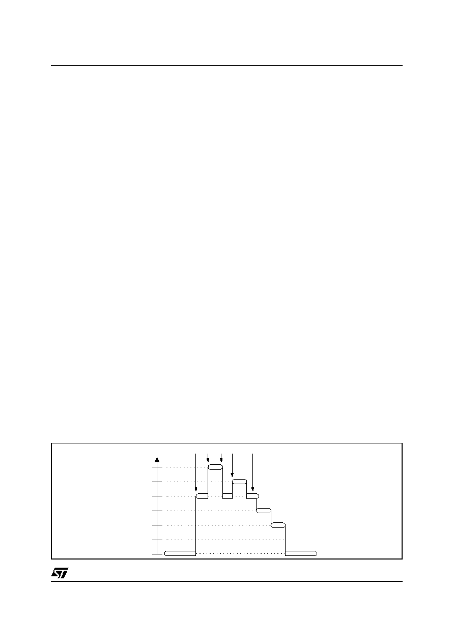
Figure 5.3 Example of Interrupt Requests
5.4 Interrupt Maskability and Priority Levels
Interrupts can be masked by the corresponding
INT_MASK Configuration Register 0 (00h). An
interrupt is enabled when the mask bit is “1". Vice
versa, when the bit is “0”, the interrupt is masked
and the eventual requests are kept pending.
All the interrupts, with the exception of the NMI and
TRAP that have fixed level priority, have a
configurable priority level. The configuration of the
priority levels is completed by writing three
consecutive Configuration Registers: INT_PRL_L,
INT_PRL_M, INT_PRL_H, addresses from 2 to 4
(02h-04h). The 24 bits of these registers are
divided into 8 groups of three bits: each group is
associated with a priority level. The three bits of
each group are written with the code number
associated with the interrupt source. See Table 5.1
to know the codes.
Warning:
The
priority
levels
Configuration
Registers must be programmed with different
values for each 3-bit groups to avoid erroneous
operation. After the RESET the priority registers
are loaded with a default priority configuration.
Each time the priority is modified, each priority
register must be configured with consistent values.
During program execution the interrupt priority can
only be modified within the Main Program: it cannot
be changed within an interrupt service routine. In
addition the interrupts must be disabled by means
of the UDGI instruction. In order to avoid side effect
the interrupts must be disabled before the priority
register configuration.
5.5 Interrupt RESET
When an interrupt is masked, all requests are not
acknowledged and remain pending. When the
pending interrupt is enabled it is immediately
serviced, if it has proper priority. This event may be
undesired; in order to avoid this a RINT instruction
may be inserted followed by the code number that
identifies the interrupt to reset the pending request.
The RINT instruction has no effect if the interrupt is
being serviced
See Table 5.1 to know the codes.
MAIN PROGRAM
5
4
3
2
1
0
INT2
INT0
INT2
INT1
INT2
INT3
INT4
MAIN PROGRAM
PRIORITY
LEVEL
INT2
INT0
INT4
INT1
INT3
6
相关PDF资料 |
PDF描述 |
|---|---|
| ST52E430B/D | 8-BIT, UVPROM, 20 MHz, MICROCONTROLLER, CDIP32 |
| ST52F510F1M6 | 8-BIT, FLASH, 24 MHz, MICROCONTROLLER, PDSO20 |
| ST52F510G0B6 | 8-BIT, FLASH, 24 MHz, MICROCONTROLLER, PDIP28 |
| ST52F513F0M6 | 8-BIT, FLASH, 24 MHz, MICROCONTROLLER, PDSO20 |
| ST52F513F1B6 | 8-BIT, FLASH, 24 MHz, MICROCONTROLLER, PDIP20 |
相关代理商/技术参数 |
参数描述 |
|---|---|
| ST52510G2 | 制造商:未知厂家 制造商全称:未知厂家 功能描述:8-BIT ICU WITH 10-BIT ADC. TWO TIMERS/PWM. I2C. SPI. SCI. UP TO 8K FLASH |
| ST52510G3 | 制造商:未知厂家 制造商全称:未知厂家 功能描述:8-BIT ICU WITH 10-BIT ADC. TWO TIMERS/PWM. I2C. SPI. SCI. UP TO 8K FLASH |
| ST52510K2 | 制造商:未知厂家 制造商全称:未知厂家 功能描述:8-BIT ICU WITH 10-BIT ADC. TWO TIMERS/PWM. I2C. SPI. SCI. UP TO 8K FLASH |
| ST52510K3 | 制造商:未知厂家 制造商全称:未知厂家 功能描述:8-BIT ICU WITH 10-BIT ADC. TWO TIMERS/PWM. I2C. SPI. SCI. UP TO 8K FLASH |
| ST52510Y2 | 制造商:未知厂家 制造商全称:未知厂家 功能描述:8-BIT ICU WITH 10-BIT ADC. TWO TIMERS/PWM. I2C. SPI. SCI. UP TO 8K FLASH |
发布紧急采购,3分钟左右您将得到回复。