- 您现在的位置:买卖IC网 > PDF目录271212 > ST72F324BK6TATRE (STMICROELECTRONICS) 8-BIT, FLASH, 8 MHz, MICROCONTROLLER, PQFP32 PDF资料下载
参数资料
| 型号: | ST72F324BK6TATRE |
| 厂商: | STMICROELECTRONICS |
| 元件分类: | 微控制器/微处理器 |
| 英文描述: | 8-BIT, FLASH, 8 MHz, MICROCONTROLLER, PQFP32 |
| 封装: | 7 X 7 MM, ROHS COMPLIANT, LQFP-32 |
| 文件页数: | 146/197页 |
| 文件大小: | 3593K |
| 代理商: | ST72F324BK6TATRE |
第1页第2页第3页第4页第5页第6页第7页第8页第9页第10页第11页第12页第13页第14页第15页第16页第17页第18页第19页第20页第21页第22页第23页第24页第25页第26页第27页第28页第29页第30页第31页第32页第33页第34页第35页第36页第37页第38页第39页第40页第41页第42页第43页第44页第45页第46页第47页第48页第49页第50页第51页第52页第53页第54页第55页第56页第57页第58页第59页第60页第61页第62页第63页第64页第65页第66页第67页第68页第69页第70页第71页第72页第73页第74页第75页第76页第77页第78页第79页第80页第81页第82页第83页第84页第85页第86页第87页第88页第89页第90页第91页第92页第93页第94页第95页第96页第97页第98页第99页第100页第101页第102页第103页第104页第105页第106页第107页第108页第109页第110页第111页第112页第113页第114页第115页第116页第117页第118页第119页第120页第121页第122页第123页第124页第125页第126页第127页第128页第129页第130页第131页第132页第133页第134页第135页第136页第137页第138页第139页第140页第141页第142页第143页第144页第145页当前第146页第147页第148页第149页第150页第151页第152页第153页第154页第155页第156页第157页第158页第159页第160页第161页第162页第163页第164页第165页第166页第167页第168页第169页第170页第171页第172页第173页第174页第175页第176页第177页第178页第179页第180页第181页第182页第183页第184页第185页第186页第187页第188页第189页第190页第191页第192页第193页第194页第195页第196页第197页
Obsolete
Product(s)
- Obsolete
Product(s)
Interrupts
ST72324B-Auto
7.5.2
Interrupt software priority registers (ISPRx)
These four registers contain the interrupt software priority of each interrupt vector.
●
Each interrupt vector (except reset and TRAP) has corresponding bits in these
registers where its own software priority is stored. This correspondence is shown in the
following Table 17.
●
Each I1_x and I0_x bit value in the ISPRx registers has the same meaning as the I1
and I0 bits in the CC register.
●
Level 0 cannot be written (I1_x = 1, I0_x = 0). In this case, the previously stored value
is kept (for example, previous value = CFh, write = 64h, result = 44h).
The reset, and TRAP vectors have no software priorities. When one is serviced, the I1 and
I0 bits of the CC register are both set.
Caution:
If the I1_x and I0_x bits are modified while the interrupt x is executed the following behavior
has to be considered: If the interrupt x is still pending (new interrupt or flag not cleared) and
the new software priority is higher than the previous one, the interrupt x is re-entered.
Otherwise, the software priority stays unchanged up to the next interrupt request (after the
IRET of the interrupt x).
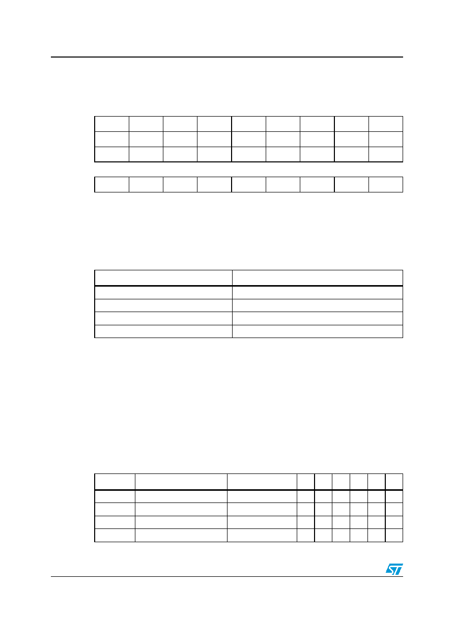
ISPRx
Reset value: 1111 1111 (FFh)
7654321
0
ISPR0
I1_3
I0_3
I1_2
I0_2
I1_1
I0_1
I1_0
I0_0
ISPR1
I1_7
I0_7
I1_6
I0_6
I1_5
I0_5
I1_4
I0_4
ISPR2
I1_11
I0_11
I1_10
I0_10
I1_9
I0_9
I1_8
I0_8
R/WR/W
R/W
ISPR3
1111
I1_13
I0_13
I1_12
I0_12
RO
R/W
Table 17.
ISPRx interrupt vector correspondence
Vector address
ISPRx bits
FFFBh-FFFAh
I1_0 and I0_0 bits
FFF9h-FFF8h
I1_1 and I0_1 bits
...
FFE1h-FFE0h
I1_13 and I0_13 bits
Table 18.
Dedicated interrupt instruction set(1)
Instruction
New description
Function/example
I1
H
I0
N
Z
C
HALT
Entering HALT mode
1
0
IRET
Interrupt routine return
POP CC, A, X, PC
I1
H
I0
N
Z
C
JRM
Jump if I1:0=11 (level 3)
I1:0=11 ?
JRNM
Jump if I1:0<>11
I1:0<>11 ?
相关PDF资料 |
PDF描述 |
|---|---|
| SAB-C161K-LMHA | 16-BIT, 20 MHz, MICROCONTROLLER, PQFP80 |
| ST72P561R4TA/XXX | 8-BIT, MROM, 8 MHz, MICROCONTROLLER, PQFP64 |
| ST7263BH4T1/XXX | 8-BIT, MROM, 8 MHz, MICROCONTROLLER, PQFP48 |
| S912XDT384J1VAGR | 16-BIT, FLASH, 40 MHz, MICROCONTROLLER, PQFP144 |
| SC101161DGCFUR2 | 16-BIT, FLASH, 25 MHz, MICROCONTROLLER, PQFP80 |
相关代理商/技术参数 |
参数描述 |
|---|---|
| ST72F324BK6TAXS | 制造商:STMicroelectronics 功能描述: |
| ST72F324BK6TCE | 制造商:STMicroelectronics 功能描述: |
| ST72F324BK6TCS | 制造商:STMicroelectronics 功能描述:APG |
| ST72F324BK6TCTRE | 制造商:STMicroelectronics 功能描述:LQFP 32 7x7x1.4 1 |
| ST72F324J2B6 | 制造商:STMicroelectronics 功能描述: |
发布紧急采购,3分钟左右您将得到回复。