- 您现在的位置:买卖IC网 > PDF目录385871 > ST72T85A5Q6 (意法半导体) 8-BIT MCU FOR RDS WITH 48K ROM, 3K RAM, ADC, TWO TIMERS, TWO SPIs, I2C AND SCI INTERFACES PDF资料下载
参数资料
| 型号: | ST72T85A5Q6 |
| 厂商: | 意法半导体 |
| 英文描述: | 8-BIT MCU FOR RDS WITH 48K ROM, 3K RAM, ADC, TWO TIMERS, TWO SPIs, I2C AND SCI INTERFACES |
| 中文描述: | 8位微控制器48,000铁路发展策略光盘,3K内存,ADC,两个定时器,2个SPI,I2C和脊髓损伤接口 |
| 文件页数: | 19/117页 |
| 文件大小: | 748K |
| 代理商: | ST72T85A5Q6 |
第1页第2页第3页第4页第5页第6页第7页第8页第9页第10页第11页第12页第13页第14页第15页第16页第17页第18页当前第19页第20页第21页第22页第23页第24页第25页第26页第27页第28页第29页第30页第31页第32页第33页第34页第35页第36页第37页第38页第39页第40页第41页第42页第43页第44页第45页第46页第47页第48页第49页第50页第51页第52页第53页第54页第55页第56页第57页第58页第59页第60页第61页第62页第63页第64页第65页第66页第67页第68页第69页第70页第71页第72页第73页第74页第75页第76页第77页第78页第79页第80页第81页第82页第83页第84页第85页第86页第87页第88页第89页第90页第91页第92页第93页第94页第95页第96页第97页第98页第99页第100页第101页第102页第103页第104页第105页第106页第107页第108页第109页第110页第111页第112页第113页第114页第115页第116页第117页
19/117
ST7285C
3.4 WATCHDOG TIMER SYSTEM (WDG)
3.4.1 Introduction
The Watchdog timer is used to detect the oc-
curence of a software fault, usually generated by
external interference or by unforeseen logical con-
ditions, which causes the application program to
abandon its normal sequence. The Watchdog cir-
cuit generates an MCU reset on expiry of a pro-
grammed time period, unless the program refresh-
es the counter’s contents before it is decremented
to zero.
3.4.2 Functional Description
The counter is decremented every 12,288 ma-
chine cycles, and the length of the timeout period
can be programmed by the user in 64 increments,
ranging from 12,288 machine cycles to 786,432
machine cycles, depending on the value loaded in
bits 0-5 of the Watchdog register. The application
program must be written so that the Watchdog
register is reloaded at regular intervals during nor-
mal operation.
The Watchdog is not activated automatically on
Reset, and must be activated by the user program
if required. Once activated it cannot be disabled,
save by a Reset.
During the Reset cycle, the device Reset pin acts
as an output that is pulsed low for 3 machine cy-
cles (6 oscillator cycles). In its high state, an inter-
nal pull-up resistor ofabout 100K
is connected to
the Reset pin.
This resistor can be pulled low by external circuitry
to reset the device.
The Watchdog delay time is defined by bits 5-0 of
the Watchdog register; bit 6 must always be set in
order to avoid generating an immediate reset.
Conversely, this can be used to generate a soft-
ware reset (bit 7 = 1, bit 6 = 0).
Once bit 7 is set, it cannot be cleared by software:
i.e. the Watchdog cannot be disabled by software
without generating a Reset. The Watchdog timer
mustbe reloaded before bit 6 is decremented to”0”
to avoid a Reset. Following a Reset, the Watchdog
register will contain 7Fh (bits 0-6 = 1, bit 7 = 0).
If the Watchdog is activated, the HALT instruction
will generate a Reset.
If the circuit is not used as a Watchdog (i.e. bit 7 is
never set), bits 6 to 0 may be used as a simple 7-
bit timer, for instance as a real time clock. Since no
interrupt will be generated under these conditions,
the Watchdog register must be monitored by soft-
ware.
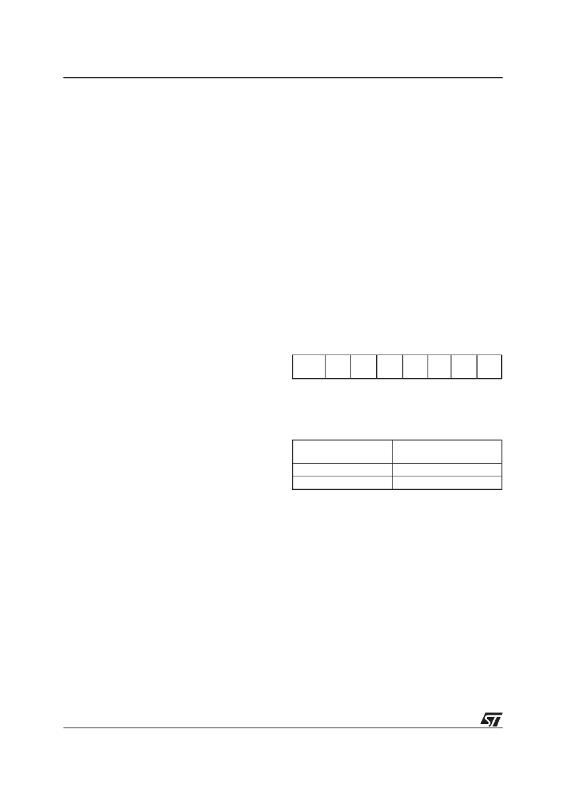
3.4.3 Watchdog Register
Register Address: 0024h
Reset Value: 0111 1111 (7Fh)
—
Read/Write
b7 =
WDGA:
Activation bit (is active if set)
b6-0 =
T6-T0
: 7-bit timer counter (Msb to Lsb)
Table 4. Watchdog Timing (f
OSC
= 8 MHz)
7
0
WDGA
T6
T5
T4
T3
T2
T1
T0
WDG Register initial
value
FF
C0
WDG timeout period (ms)
197
3
相关PDF资料 |
PDF描述 |
|---|---|
| ST730C08L3 | PHASE CONTROL THYRISTORS |
| ST730C08L3L | PHASE CONTROL THYRISTORS |
| ST730C12L0 | PHASE CONTROL THYRISTORS |
| ST730C12L0L | PHASE CONTROL THYRISTORS |
| ST730C12L1 | PHASE CONTROL THYRISTORS |
相关代理商/技术参数 |
参数描述 |
|---|---|
| ST730 | 制造商:IRF 制造商全称:International Rectifier 功能描述:PHASE CONTROL THYRISTORS Hockey Puk Version |
| ST7-30 | 制造商:SUPERWORLD 制造商全称:Superworld Electronics 功能描述:POWER TRANSFORMER |
| ST-7300 | 制造商:GC Electronics 功能描述: |
| ST730186-3 | 制造商:KEMET Corporation 功能描述: 制造商:KET 功能描述: |
| ST730268-1 | 制造商:KEMET Corporation 功能描述: 制造商:KET 功能描述: |
发布紧急采购,3分钟左右您将得到回复。