- 您现在的位置:买卖IC网 > PDF目录11767 > AD9882KSTZ-100 (Analog Devices Inc)IC INTERFACE/DVI 100MHZ 100LQFP PDF资料下载
参数资料
| 型号: | AD9882KSTZ-100 |
| 厂商: | Analog Devices Inc |
| 文件页数: | 40/40页 |
| 文件大小: | 0K |
| 描述: | IC INTERFACE/DVI 100MHZ 100LQFP |
| 标准包装: | 1 |
| 应用: | 视频 |
| 接口: | 模拟,DVI |
| 电源电压: | 3.15 V ~ 3.45 V |
| 封装/外壳: | 100-LQFP |
| 供应商设备封装: | 100-LQFP(14x14) |
| 包装: | 管件 |
| 安装类型: | 表面贴装 |
第1页第2页第3页第4页第5页第6页第7页第8页第9页第10页第11页第12页第13页第14页第15页第16页第17页第18页第19页第20页第21页第22页第23页第24页第25页第26页第27页第28页第29页第30页第31页第32页第33页第34页第35页第36页第37页第38页第39页当前第40页
AD9882A
Rev. 0 | Page 9 of 40
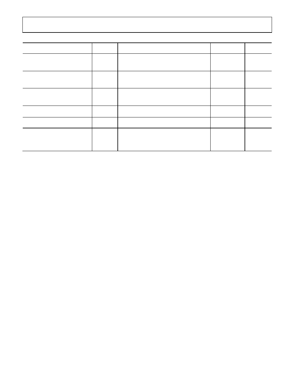
Table 5. Analog Interface Pin List
Pin Type
Mnemonic
Function
Value
Pin
Number
Analog Video Inputs
RAIN
Analog input for Converter R
0.0 V to 1.0 V
70
GAIN
Analog input for Converter G
0.0 V to 1.0 V
65
BAIN
Analog input for Converter B
0.0 V to 1.0 V
59
External Sync/Clock
HSYNC
Horizontal SYNC input
3.3 V CMOS
79
VSYNC
Vertical SYNC input
3.3 V CMOS
80
SOGIN
Sync-on-green input
0.0 V to 1.0 V
64
Sync Outputs
HSOUT
Hsync output (phase-aligned with DATACK)
3.3 V CMOS
88
VSOUT
Vsync output
3.3 V CMOS
87
SOGOUT
Composite SYNC
3.3 V CMOS
89
Voltage Reference Clamp Voltages
REFBYPASS
Internal reference bypass
1.25 V
73
MIDBYPASS
Internal midscale voltage bypass
74
PLL Filter
FILT
Connection for external filter components for
internal PLL
48
Power Supply
VD
Main power supply
3.15 V to 3.45 V
PVD
PLL power supply (nominally 3.3 V)
3.15 V to 3.45 V
VDD
Output power supply
2.2 V to 3.6 V
GND
Ground
0 V
PIN FUNCTION DETAIL: ANALOG INTERFACE
Inputs
RAIN—Analog Input for Red Channel
GAIN—Analog Input for Green Channel
BAIN—Analog Input for Blue Channel
High impedance inputs that accept the red, green, and blue
channel graphics signals, respectively. For RGB, the three
channels are identical and can be used for any colors, but colors
are assigned for convenient reference.
For proper 4:2:2 formatting in a YPbPr application, the Y must
be connected to the GAIN input, the Pb must be connected to the
BAIN input, and the Pr must be connected to the RAIN input.
They accommodate input signals ranging from 0.5 V to 1.0 V
full scale. Signals should be ac-coupled to these pins to support
clamp operation.
Hsync—Horizontal Sync Input
This input receives a logic signal that establishes the horizontal
timing reference and provides the frequency reference for pixel
clock generation. The logic sense of this pin is controlled by
Serial Register Bit 0x10, Bit 6 (Hsync polarity). Only the leading
edge of Hsync is used by the PLL; the trailing edge is used for
clamp timing. When Hsync polarity = 0, the falling edge of
Hsync is used. When Hsync polarity = 1, the rising edge is
active.
The input includes a Schmitt trigger for noise immunity, with a
nominal input threshold of 1.5 V.
Electrostatic discharge (ESD) protection diodes conduct heavily
if this pin is driven more than 0.5 V above the maximum
tolerance voltage (3.3 V) or more than 0.5 V below ground.
VSYNC—Vertical Sync Input
This is the input for vertical sync.
SOGIN—Sync-on-Green Input
This input is provided to assist with processing signals with
embedded sync, typically on the green channel. The pin is
connected to a high speed comparator with an internally
generated threshold, which is set by the value of Register 0x0F,
Bits 7 to 3.
When connected to an ac-coupled graphics signal with
embedded sync, it produces a noninverting digital output
on SOGOUT.
When not used, this input should be left unconnected. For
more details on this function and how it should be configured,
refer to the Sync-on-Green (SOG) section.
SOGOUT—Sync-on-Green Slicer Output
This pin can be programmed to produce either the output from
the sync-on-green slicer comparator or an unprocessed but
delayed version of the Hsync input. See Figure 20, the sync
processing block diagram, to view how this pin is connected.
Note that the output from this pin is the composite sync
without additional processing from the AD9882A.
相关PDF资料 |
PDF描述 |
|---|---|
| MS27473E16B55PA | CONN PLUG 55POS STRAIGHT W/PINS |
| LTC4305IGN#TR | IC BUFFER BUS 2WR ADDRESS 16SSOP |
| VI-B43-IW-F2 | CONVERTER MOD DC/DC 24V 100W |
| AD9983AKCPZ-170 | IC INTRFACE 8BIT 170MSPS 64LFCSP |
| VI-B42-IX-F4 | CONVERTER MOD DC/DC 15V 75W |
相关代理商/技术参数 |
参数描述 |
|---|---|
| AD9882KSTZ-140 | 功能描述:IC INTERFACE/DVI 100MHZ 100LQFP RoHS:是 类别:集成电路 (IC) >> 接口 - 专用 系列:- 特色产品:NXP - I2C Interface 标准包装:1 系列:- 应用:2 通道 I²C 多路复用器 接口:I²C,SM 总线 电源电压:2.3 V ~ 5.5 V 封装/外壳:16-TSSOP(0.173",4.40mm 宽) 供应商设备封装:16-TSSOP 包装:剪切带 (CT) 安装类型:表面贴装 产品目录页面:825 (CN2011-ZH PDF) 其它名称:568-1854-1 |
| AD9883 | 制造商:AD 制造商全称:Analog Devices 功能描述:110 MSPS Analog Interface for Flat Panel Displays |
| AD9883/PCB | 制造商:AD 制造商全称:Analog Devices 功能描述:110 MSPS Analog Interface for Flat Panel Displays |
| AD9883A | 制造商:AD 制造商全称:Analog Devices 功能描述:110 MSPS/140 MSPS Analog Interface for Flat Panel Displays |
| AD9883A/PCB | 制造商:Analog Devices 功能描述:110MHZ ANALOG INTERFACE FOR SG |
发布紧急采购,3分钟左右您将得到回复。