- 您现在的位置:买卖IC网 > PDF目录294980 > AGL10002-FFGG256 FPGA, 1000000 GATES, 200 MHz, PBGA144 PDF资料下载
参数资料
| 型号: | AGL10002-FFGG256 |
| 元件分类: | FPGA |
| 英文描述: | FPGA, 1000000 GATES, 200 MHz, PBGA144 |
| 封装: | 13 X 13 MM, 1 MM PITCH, ROHS COMPLIANT, FBGA-144 |
| 文件页数: | 176/204页 |
| 文件大小: | 2800K |
| 代理商: | AGL10002-FFGG256 |
第1页第2页第3页第4页第5页第6页第7页第8页第9页第10页第11页第12页第13页第14页第15页第16页第17页第18页第19页第20页第21页第22页第23页第24页第25页第26页第27页第28页第29页第30页第31页第32页第33页第34页第35页第36页第37页第38页第39页第40页第41页第42页第43页第44页第45页第46页第47页第48页第49页第50页第51页第52页第53页第54页第55页第56页第57页第58页第59页第60页第61页第62页第63页第64页第65页第66页第67页第68页第69页第70页第71页第72页第73页第74页第75页第76页第77页第78页第79页第80页第81页第82页第83页第84页第85页第86页第87页第88页第89页第90页第91页第92页第93页第94页第95页第96页第97页第98页第99页第100页第101页第102页第103页第104页第105页第106页第107页第108页第109页第110页第111页第112页第113页第114页第115页第116页第117页第118页第119页第120页第121页第122页第123页第124页第125页第126页第127页第128页第129页第130页第131页第132页第133页第134页第135页第136页第137页第138页第139页第140页第141页第142页第143页第144页第145页第146页第147页第148页第149页第150页第151页第152页第153页第154页第155页第156页第157页第158页第159页第160页第161页第162页第163页第164页第165页第166页第167页第168页第169页第170页第171页第172页第173页第174页第175页当前第176页第177页第178页第179页第180页第181页第182页第183页第184页第185页第186页第187页第188页第189页第190页第191页第192页第193页第194页第195页第196页第197页第198页第199页第200页第201页第202页第203页第204页
IGLOO Low-Power Flash FPGAs with Flash*Freeze Technology
A d v an c ed v0 . 1
2-59
Actel recommends that VPUMP and VJTAG power supplies
are kept separate with independent filtering capacitors
rather than supplying them from a common rail.
User Pins
I/O
User Input/Output
The I/O pin functions as an input, output, tristate, or
bidirectional buffer. Input and output signal levels are
compatible with the I/O standard selected.
During programming, I/Os become tristated and weakly
pulled up to VCCI. With VCCI, VMV, and VCC supplies
continuously powered up, when the device transitions
from programming to operating mode, the I/Os are
instantly configured to the desired user configuration.
Unused I/Os are configured as follows:
Output buffer is disabled (with tristate value of high
impedance).
Input buffer is disabled (with tristate value of high
impedance).
Weak pull-up is programmed.
GL
Globals
GL I/Os have access to certain clock conditioning circuitry
(and the PLL) and/or have direct access to the global
network (spines). Additionally, the global I/Os can be
used as I/Os, since they have identical capabilities.
Unused GL pins are configured as inputs with pull-up
resistors. See more detailed descriptions of global I/O
connectivity in the "Clock Conditioning Circuits" section
on page 2-14. All inputs labeled GC/GF are direct inputs
into the quadrant clocks. For example, if GAA0 is used
for an input, GAA1 and GAA2 are no longer available for
input to the quadrant globals. All inputs labeled GC/GF
are direct input into the chip-level globals, and the rest
are connected to the quadrant globals. The inputs to the
global network are multiplexed, and only one input can
be used as a global input.
Refer to the "User I/O Naming Convention" section on
page 2-56 for an explanation of the naming of global
pins.
FF
Flash*Freeze Mode Activation Pin
The FF pin is a dedicated input pin that is used to enter
and exit Flash*Freeze mode. The FF pin is active low, has
the same characteristics as a single-ended I/O, and must
meet
the
maximum
rise
and
fall
time.
When
Flash*Freeze mode is not used in the design, the FF pin is
available as a regular I/O.
When Flash*Freeze mode is used, the FF pin must not be
left floating to avoid accidentally entering Flash*Freeze
mode. While in Flash*Freeze mode, the Flash*Freeze pin
should be constantly asserted.
The Flash*Freeze pin can be used with any single-ended
I/O standard supported by the I/O bank in which the pin
is located, and input signal levels compatible with the I/O
standard selected. The FF pin should be treated as a
sensitive
asynchronous
signal.
When
defining
pin
placement and board layout, simultaneously switching
outputs
(SSOs)
and
their
effects
on
sensitive
asynchronous pins must be considered.
Unused FF or I/O pins are tristated with weak pull-up.
This default configuration applies to both Flash*Freeze
mode and normal operation mode. No user intervention
is required.
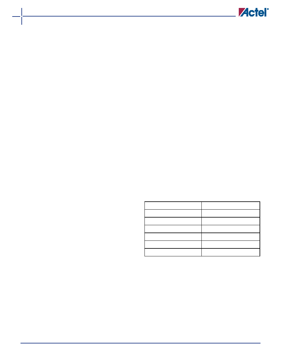
Table 2-32 shows the Flash*Freeze pin location on the
available packages for IGLOO devices. The Flash*Freeze
pin
location
is
independent
of
device,
allowing
migration to larger or smaller IGLOO devices while
maintaining the same pin location on the board.
Table 2-32 Flash*Freeze Pin Location in IGLOO Family
Packages (device-independent)
Package
Flash*Freeze Pin
CS196
TBD
QN132
B12
VQ100
27
FG144
L3
FG256
T3
FG484
W6
相关PDF资料 |
PDF描述 |
|---|---|
| AGL10002-FFGG484I | FPGA, 1000000 GATES, 200 MHz, PBGA484 |
| AGL10002-FFGG484 | FPGA, 1000000 GATES, 200 MHz, PBGA484 |
| AGL10002-FG144I | FPGA, 1000000 GATES, 200 MHz, PBGA144 |
| AGL10002-FG144 | FPGA, 1000000 GATES, 200 MHz, PBGA144 |
| AGL10002-FG256I | FPGA, 1000000 GATES, 200 MHz, PBGA144 |
相关代理商/技术参数 |
参数描述 |
|---|---|
| AGL1000V2-CS144 | 制造商:ACTEL 制造商全称:Actel Corporation 功能描述:IGLOO Low-Power Flash FPGAs with Flash Freeze Technology |
| AGL1000V2-CS144ES | 制造商:ACTEL 制造商全称:Actel Corporation 功能描述:IGLOO Low-Power Flash FPGAs with Flash Freeze Technology |
| AGL1000V2-CS144I | 制造商:ACTEL 制造商全称:Actel Corporation 功能描述:IGLOO Low-Power Flash FPGAs with Flash Freeze Technology |
| AGL1000V2-CS144PP | 制造商:ACTEL 制造商全称:Actel Corporation 功能描述:IGLOO Low-Power Flash FPGAs with Flash Freeze Technology |
| AGL1000V2-CS281 | 功能描述:IC FPGA 1KB FLASH 1M 281-CSP RoHS:否 类别:集成电路 (IC) >> 嵌入式 - FPGA(现场可编程门阵列) 系列:IGLOO 标准包装:40 系列:SX-A LAB/CLB数:6036 逻辑元件/单元数:- RAM 位总计:- 输入/输出数:360 门数:108000 电源电压:2.25 V ~ 5.25 V 安装类型:表面贴装 工作温度:0°C ~ 70°C 封装/外壳:484-BGA 供应商设备封装:484-FPBGA(27X27) |
发布紧急采购,3分钟左右您将得到回复。