- 您现在的位置:买卖IC网 > PDF目录296941 > QL8150-6PT280I (QUICKLOGIC CORP) FPGA, 640 CLBS, 188946 GATES, PBGA280 PDF资料下载
参数资料
| 型号: | QL8150-6PT280I |
| 厂商: | QUICKLOGIC CORP |
| 元件分类: | FPGA |
| 英文描述: | FPGA, 640 CLBS, 188946 GATES, PBGA280 |
| 封装: | 0.80 MM PITCH, LFBGA-280 |
| 文件页数: | 78/96页 |
| 文件大小: | 1607K |
| 代理商: | QL8150-6PT280I |
第1页第2页第3页第4页第5页第6页第7页第8页第9页第10页第11页第12页第13页第14页第15页第16页第17页第18页第19页第20页第21页第22页第23页第24页第25页第26页第27页第28页第29页第30页第31页第32页第33页第34页第35页第36页第37页第38页第39页第40页第41页第42页第43页第44页第45页第46页第47页第48页第49页第50页第51页第52页第53页第54页第55页第56页第57页第58页第59页第60页第61页第62页第63页第64页第65页第66页第67页第68页第69页第70页第71页第72页第73页第74页第75页第76页第77页当前第78页第79页第80页第81页第82页第83页第84页第85页第86页第87页第88页第89页第90页第91页第92页第93页第94页第95页第96页
2007 QuickLogic Corporation
Eclipse II Family Data Sheet Rev. Q
8
F
in represents a very stable high-frequency input clock and produces an accurate signal reference. This signal
can either bypass the PLL entirely, thus entering the clock tree directly, or it can pass through the PLL itself.
Within the PLL, a voltage-controlled oscillator (VCO) is added to the circuit. The external F
in signal and the
local VCO form a control loop. The VCO is multiplied or divided down to the reference frequency, so that a
phase detector (the crossed circle in Figure 6) can compare the two signals. If the phases of the external and
local signals are not within the tolerance required, the phase detector sends a signal through the charge pump
and loop filter (Figure 6). The charge pump generates an error voltage to bring the VCO back into alignment,
and the loop filter removes any high frequency noise before the error voltage enters the VCO. This new VCO
signal enters the clock tree to drive the chip's circuitry.
F
out represents the clock signal emerging from the output pad (the output signal PLLPAD_OUT is explained
in Table 7). The PLL always drives the PLLPAD_OUT signal, regardless of whether the PLL is configured for
on-chip use. The PLLPAD_OUT will not oscillate if PLL_RESET is asserted, or if the PLL is powered down.
The QL8325 and QL8250 devices contain four PLLs, the remaining Eclipse II devices do not contain PLLs.
There is one PLL located in each quadrant of the FPGA. QuickLogic PLLs compensate for the additional delay
created by the clock tree itself, as previously noted, by subtracting the clock tree delay through the feedback
path.
PLL Modes of Operation
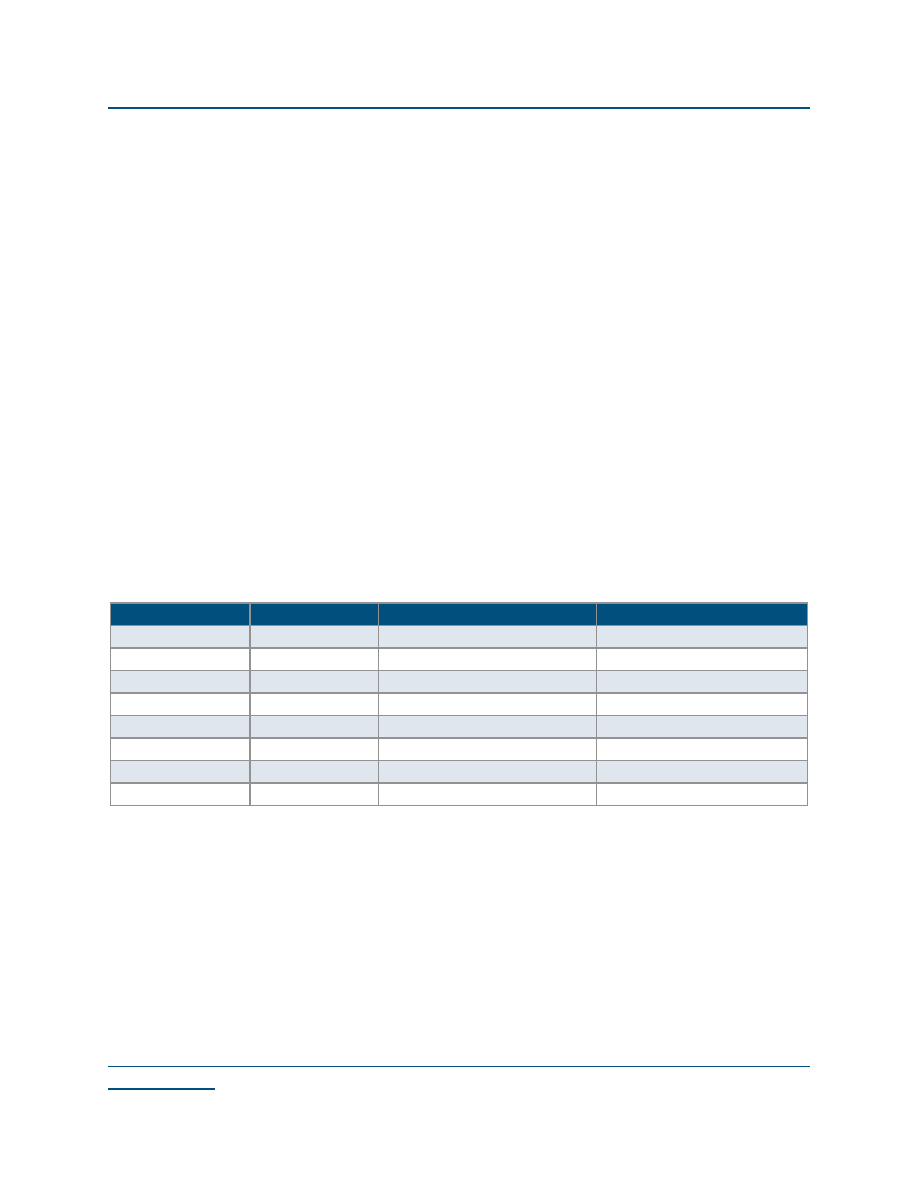
QuickLogic PLLs have eight modes of operation, based on the input frequency and desired output frequency—
Table 6 indicates the features of each mode.
NOTE: “HF” stands for “high frequency” and “LF” stands for “low frequency.”
The input frequency can range from 12.5 MHz to 440 MHz, while output frequency ranges from 25 MHz to
220 MHz. When adding PLLs to the top-level design, be sure that the PLL mode matches the desired input
and output frequencies.
Table 6: PLL Mode Frequencies
PLL Model
Output Frequency
Input Frequency Range
Output Frequency Range
PLL_HF
Same as input
66 MHz–220 MHz
PLL_LF
Same as input
25 MHz–66 MHz
PLL_MULT2HF
2x
33 MHz–110 MHz
66 MHz–220 MHz
PLL_MULT2LF
2x
12.5 MHz–33 MHz
25 MHz–66 MHz
PLL_DIV2HF
1/2x
220 MHz–440 MHz
110 MHz–220 MHz
PLL_DIV2LF
1/2x
50 MHz–220 MHz
25 MHz–110 MHz
PLL_MULT4
4x
12.5 MHz–50 MHz
50 MHz–200 MHz
PLL_DIV4
1/4x
100 MHz–440 MHz
25 MHz–110 MHz
相关PDF资料 |
PDF描述 |
|---|---|
| QL8150-6PT280M | FPGA, 640 CLBS, 188946 GATES, PBGA280 |
| QL8150-6PTN280C | FPGA, 640 CLBS, 188946 GATES, PBGA280 |
| QL8150-6PTN280I | FPGA, 640 CLBS, 188946 GATES, PBGA280 |
| QL8150-6PTN280M | FPGA, 640 CLBS, 188946 GATES, PBGA280 |
| QL8150-6PUN196C | FPGA, 640 CLBS, 188946 GATES, PBGA196 |
相关代理商/技术参数 |
参数描述 |
|---|---|
| QL8250 | 制造商:未知厂家 制造商全称:未知厂家 功能描述:LOW POWER FPGA COMBINING PERFORMANCE DENSITY AND EMBEDED RAM |
| QL8250-6PQN208C-5690 | 制造商:QuickLogic Corporation 功能描述: |
| QL8250-6PQN208C-5691 | 制造商:QuickLogic Corporation 功能描述: |
| QL82SD | 制造商:未知厂家 制造商全称:未知厂家 功能描述:10 High Speed Bus LVDS Serial Links bandwidth up to 5 Gbps |
| QL82SD-PB516 | 制造商:未知厂家 制造商全称:未知厂家 功能描述:10 High Speed Bus LVDS Serial Links bandwidth up to 5 Gbps |
发布紧急采购,3分钟左右您将得到回复。