- 您现在的位置:买卖IC网 > PDF目录98082 > SLC88B17QFP (STANDARD MICROSYSTEMS CORP) ISA BUS CONTROLLER, PQFP160 PDF资料下载
参数资料
| 型号: | SLC88B17QFP |
| 厂商: | STANDARD MICROSYSTEMS CORP |
| 元件分类: | 总线控制器 |
| 英文描述: | ISA BUS CONTROLLER, PQFP160 |
| 封装: | QFP-160 |
| 文件页数: | 53/54页 |
| 文件大小: | 333K |
| 代理商: | SLC88B17QFP |
第1页第2页第3页第4页第5页第6页第7页第8页第9页第10页第11页第12页第13页第14页第15页第16页第17页第18页第19页第20页第21页第22页第23页第24页第25页第26页第27页第28页第29页第30页第31页第32页第33页第34页第35页第36页第37页第38页第39页第40页第41页第42页第43页第44页第45页第46页第47页第48页第49页第50页第51页第52页当前第53页第54页
SMSC DS – SLC88B17
Page 8
Rev. 09/28/99
SIGNAL DESCRIPTION
This section provides a detailed description of each SLC88B17 signal. The signals are arranged in functional groups
according to their associated function.
The ‘n’ symbol at the beginning of a signal name indicates that it is an active low signal. When ‘n’ is not present
before the signal name, it indicates an active high signal.
The terms assert or assertion indicates that a signal is active, independent of whether that level is represented by a
high or low voltage. The terms negate or negation indicates that a signal is inactive.
Certain signals have different functions, depending on the configuration programmed in the PCI configuration space.
This signal whose function is being described is in bold font.
The term High-Z means tri-stated.
The term Undefined means the signal could be high, low, tri-stated, or in some in-between level.
The following notations are used to describe the signal type.
I
Input is an input-only signal.
O
Totem pole output is a standard active driver.
I/O
Input/Output is a bi-directional, tri-state input/output pin.
OD
Open drain.
I/OD
Input/Open Drain Output is a standard input buffer with an Open Drain Output.
s/t/s
Sustained tri-state is an active low tri-state signal owned and driven by one and only one agent at a
time. The agent that drives a s/t/s pin low must drive it high for at least one clock before letting it
float. A new agent can not start driving a s/t/s signal any sooner than one clock after the previous
owner tri-states it. An external pull-up resistor is required to sustain the inactive state until another
agent drives it and must be provided by the central resource.
V
This is a power supply pin.
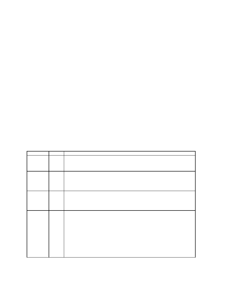
PCI INTERFACE
NAME
TYPE
DESCRIPTION
AD[31-0]
I/O
Address/Data. PCI address and data lines. Address is driven with nFRAME
asserted, data is driven or received in following clocks.
During Reset: High-Z
After Reset: High-Z
C/nBE[3-0]
I/O
Command/Byte Enable. The command is driven with nFRAME asserted, byte
enables corresponding to supplied or requested data is driven in following clocks.
C/nBE0 applies to byte 0, C/nBE1 applies to byte 1, etc.
During Reset: High-Z
After Reset: High-Z
nFRAME
I/O
FRAME. Its assertion indicates the address phase of a PCI transfer. Negation
indicates that one more data transfer will be followed. nFRAME remains tri-stated
until driven by the SLC88B17 as an initiator.
During Reset: High-Z
After Reset: High-Z
nDEVSEL
I/O
Device Select. As an output the SLC88B17 asserts nDEVSEL to claim a PCI
transaction through positive decoding (if enabled) or subtractive decoding.
The
SLC88B17 also asserts nDEVSEL when it samples IDSEL active in configuration
cycles to SLC88B17 configuration registers.
As an input, nDEVSEL indicates the response to a SLC88B17 initiated transaction
and is also sampled when deciding whether to subtractive decode the cycle.
nDEVSEL is asserted or sampled at medium decode time. It remains tri-stated until
driven by the SLC88B17 as a target.
During Reset: High-Z
After Reset: High-Z
相关PDF资料 |
PDF描述 |
|---|---|
| SLF4000L7 | 2-INPUT NAND GATE, BCC7 |
| SLHNNGAL32ANT | SINGLE COLOR LED, GREEN, 5.2 mm |
| SLHNNWH511T0S0QRC3 | SINGLE COLOR LED, WHITE, 5.6 mm |
| SLHNNWH531T0S0QRC5 | SINGLE COLOR LED, COOL WHITE, 5.6 mm |
| SLHNNWH531T0S0QRC5 | T-3 SINGLE COLOR LED, COOL WHITE, 8 mm |
相关代理商/技术参数 |
参数描述 |
|---|---|
| SLC8B1300 | 制造商:ITT 制造商全称:ITT Industries 功能描述:Snap/Clip-Lock Environmentally Sealed - Circular |
| SLC8B1310 | 制造商:ITT 制造商全称:ITT Industries 功能描述:Snap/Clip-Lock Environmentally Sealed - Circular |
| SLC8B500 | 制造商:ITT 制造商全称:ITT Industries 功能描述:Snap/Clip-Lock Environmentally Sealed - Circular |
| SLC8B510 | 制造商:ITT 制造商全称:ITT Industries 功能描述:Snap/Clip-Lock Environmentally Sealed - Circular |
| SLC8P1300 | 制造商:ITT 制造商全称:ITT Industries 功能描述:Snap/Clip-Lock Environmentally Sealed - Circular |
发布紧急采购,3分钟左右您将得到回复。