- 您现在的位置:买卖IC网 > PDF目录385871 > ST7285C (意法半导体) 8-BIT MCU FOR RDS WITH 48K ROM, 3K RAM, ADC, TWO TIMERS, TWO SPIs, I2C AND SCI INTERFACES PDF资料下载
参数资料
| 型号: | ST7285C |
| 厂商: | 意法半导体 |
| 英文描述: | 8-BIT MCU FOR RDS WITH 48K ROM, 3K RAM, ADC, TWO TIMERS, TWO SPIs, I2C AND SCI INTERFACES |
| 中文描述: | 8位微控制器48,000铁路发展策略光盘,3K内存,ADC,两个定时器,2个SPI,I2C和脊髓损伤接口 |
| 文件页数: | 76/117页 |
| 文件大小: | 748K |
| 代理商: | ST7285C |
第1页第2页第3页第4页第5页第6页第7页第8页第9页第10页第11页第12页第13页第14页第15页第16页第17页第18页第19页第20页第21页第22页第23页第24页第25页第26页第27页第28页第29页第30页第31页第32页第33页第34页第35页第36页第37页第38页第39页第40页第41页第42页第43页第44页第45页第46页第47页第48页第49页第50页第51页第52页第53页第54页第55页第56页第57页第58页第59页第60页第61页第62页第63页第64页第65页第66页第67页第68页第69页第70页第71页第72页第73页第74页第75页当前第76页第77页第78页第79页第80页第81页第82页第83页第84页第85页第86页第87页第88页第89页第90页第91页第92页第93页第94页第95页第96页第97页第98页第99页第100页第101页第102页第103页第104页第105页第106页第107页第108页第109页第110页第111页第112页第113页第114页第115页第116页第117页
76/117
ST7285C
RDS G.B.S.
(Cont’d)
GS_CNT - Count Register
b7-6 =
CNB[1;0]
free-running 2-bit counter used
as block/order counter. It is decremented on zero-
count of CNA[4:0]. The zero-counts of CNA and
CNB are used for counter interrupt generation. Re-
set Value equals one.
b5 =
SYNC:
Set to “1” whenever CNA[4;0] reach-
es a zero-count. it is valid for one period of
RDSCLK. Read only. SYNC flag is used when a
counter interrupt is desired on every RDSCLK
(used for general timing or ARI filter service), while
the BLK-SYNC interrupt service is performed eve-
ry 26 bits (CNA=26).
b4-0 =
CNA[4:0]:
5-bit r/w autoreload counter;
used as RDS bit counter It is decremented on
every rising edge of RDSCLK. When writing to
CNA, both a latch and the counter itself are writ-
ten. Immediately after reaching zero-count, the
contents of the latch are loaded back into the
counter (autoreload), so the zero-count state can
never be read by software. The zero-count of CNA
is used for counter interrupt generation. Reset Val-
ue equals one.
GS_INT - Interrupt Register
b7 =
CAL
: Start Calculation.Writing a “1” into CAL
leads to a new syndrome calculation. CAL is al-
ways read as “0”. Used in software error correc-
tion.
b6 =
CAR:
Calculation Running Set to “1” by writ-
ing CAL=1. It returns to “0” when the syndrome
calculation is complete (VSI valid). Read only.
Used in software error correction.
b5 =
ECM:
Error Correction Mode.If error correc-
tion by software is to be performed, ECM must be
set to “1”. This suppresses both shift and rotate
clocks for shift registers SR3-SR0, making them
available for software-triggered syndrome calcula-
tions which may require more than one RDSCLK
period. On completion of a correction, ECM must
be reset to “0” and the current status of SR3-SR0
must be retrieved from the shadow registers DR3-
DR0 by a copy routine.
b4 =
VSI:
Valid Syndrome Interrupt This flag is set
to “1” when the block code (BL[2:0]) is equal to one
of the six valid syndromes. Otherwise, it is reset to
“0”. VSI is valid on completion of a syndrome cal-
culation, for one period of RDSCLK. However, VSI
must be reset by software at the end of the inter-
rupt service routine. VSI and CNI interrupts are
ORed to the active-high level interrupt, ITSYNC.
b3 =
VSE:
Valid Syndrome interrupt Enable.Set-
ting VSE to “1” enables the VSI interrupt.
b2 =
CNI
: Counter Interrupt This flag is set to
“1”on the zero-count of CNA/CNB or on the rising
edge of RDSCLK, depending on the setting of
CNE[1:0]. CNI is valid on completion of the syn-
drome calculation, for one period of RDSCLK.
However, CNI must be reset by software at the
end of the interrupt service routine. VSI and CNI
interrupts are ORed to the active high level inter-
rupt ITSYNC.
b1,0 =
CNE[1:0]
. Enables and selects the counter
interrupt, see Table 11 below:
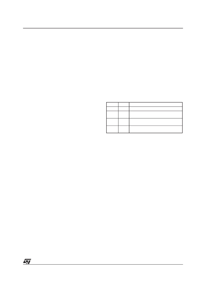
Table 11. Counter Interrupt Source Selection
DR0 - RDSDAT Register 0
b7,6 =
DR[1:0]
. Receives RDSDAT sequence.
b5 = reserved, always read as “0”.
b4 =
MQE:
Multiple Quality Error Set to “1” when
2 or more low quality bit are detected during the
last block (26 bits). MQE is valid for one period of
RDSCLK, starting with CNA zero-count and is re-
set by hardware at the end of this period.
b3 =
SQE:
Single Quality Error Set to “1” when a
low quality bit is detected during the last block (26
bits). SQE is valid for one period of RDSCLK,
starting with CNA zero-count and is reset by hard-
ware at the end of this period.
b2 =
QAL
. Transparent QUALITY input signal
from RDS demodulator; read only.
b1 =
RCL
. Transparent RDSCLK input signal from
RDS demodulator; read only.
b0 =
RDA
. Transparent RDSDAT input signal from
RDS demodulator; read only.
DRx - RDS Data Registers
DR1.
b7-0 contain bits 9-2 of a received RDSDAT
sequence.
DR2.
b7-0 contain bits 17-10 of a received RDS-
DAT sequence.
DR3.
b7-0 contain bits 18-25 of a received RDS-
DAT sequence.
CNE1
0
CNE0
0
Counter Interrupt Source Selection
counter interrupt disabled
counter interrupt onevery rising edge
of RDSCLK
counter interrupt on CNA zero-count
state
counter interrupt on CNA & CNB zero
count states
0
1
1
0
1
1
相关PDF资料 |
PDF描述 |
|---|---|
| ST72T85A5Q6 | 8-BIT MCU FOR RDS WITH 48K ROM, 3K RAM, ADC, TWO TIMERS, TWO SPIs, I2C AND SCI INTERFACES |
| ST730C08L3 | PHASE CONTROL THYRISTORS |
| ST730C08L3L | PHASE CONTROL THYRISTORS |
| ST730C12L0 | PHASE CONTROL THYRISTORS |
| ST730C12L0L | PHASE CONTROL THYRISTORS |
相关代理商/技术参数 |
参数描述 |
|---|---|
| ST7-28B56 | 功能描述:电源变压器 SPLIT BOBBIN HORZ MOUNT XFMR RoHS:否 制造商:Triad Magnetics 功率额定值:12 VA 初级电压额定值:115 V / 230 V 次级电压额定值:12 V / 24 V 安装风格:SMD/SMT 一次绕组:Dual Primary Winding 二次绕组:Dual Secondary Winding 长度:2.5 in 宽度:2 in 高度:1.062 in |
| ST72A | 制造商:DGS 功能描述: |
| ST72C104G1B6 | 功能描述:8位微控制器 -MCU Flash 4K SPI RoHS:否 制造商:Silicon Labs 核心:8051 处理器系列:C8051F39x 数据总线宽度:8 bit 最大时钟频率:50 MHz 程序存储器大小:16 KB 数据 RAM 大小:1 KB 片上 ADC:Yes 工作电源电压:1.8 V to 3.6 V 工作温度范围:- 40 C to + 105 C 封装 / 箱体:QFN-20 安装风格:SMD/SMT |
| ST72C104G1M1 | 制造商:STMicroelectronics 功能描述:8-BIT MICROCONTROLLER - Bulk |
| ST72C104G1M6 | 功能描述:8位微控制器 -MCU Flash 4K SPI RoHS:否 制造商:Silicon Labs 核心:8051 处理器系列:C8051F39x 数据总线宽度:8 bit 最大时钟频率:50 MHz 程序存储器大小:16 KB 数据 RAM 大小:1 KB 片上 ADC:Yes 工作电源电压:1.8 V to 3.6 V 工作温度范围:- 40 C to + 105 C 封装 / 箱体:QFN-20 安装风格:SMD/SMT |
发布紧急采购,3分钟左右您将得到回复。