- 您现在的位置:买卖IC网 > PDF目录15166 > ZL6105ALAFTK (Intersil)IC REG CTRLR BUCK PWM VM 36-QFN PDF资料下载
参数资料
| 型号: | ZL6105ALAFTK |
| 厂商: | Intersil |
| 文件页数: | 24/35页 |
| 文件大小: | 0K |
| 描述: | IC REG CTRLR BUCK PWM VM 36-QFN |
| 标准包装: | 1,000 |
| PWM 型: | 电压模式 |
| 输出数: | 1 |
| 频率 - 最大: | 1.4MHz |
| 占空比: | 95% |
| 电源电压: | 3 V ~ 14 V |
| 降压: | 是 |
| 升压: | 无 |
| 回扫: | 无 |
| 反相: | 无 |
| 倍增器: | 无 |
| 除法器: | 无 |
| Cuk: | 无 |
| 隔离: | 无 |
| 工作温度: | -40°C ~ 85°C |
| 封装/外壳: | 36-VFQFN 裸露焊盘 |
| 包装: | 带卷 (TR) |
第1页第2页第3页第4页第5页第6页第7页第8页第9页第10页第11页第12页第13页第14页第15页第16页第17页第18页第19页第20页第21页第22页第23页当前第24页第25页第26页第27页第28页第29页第30页第31页第32页第33页第34页第35页
�� �
�
�ZL6105�
�Thermal� Overload� Protection�
�The� ZL6105� includes� an� on-chip� thermal� sensor� that�
�continuously� measures� the� internal� temperature� of� the� die� and�
�shuts� down� the� device� when� the� temperature� exceeds� the� preset�
�limit.� The� default� temperature� limit� is� set� to� +125°C� in� the�
�factory,� but� the� user� may� set� the� limit� to� a� different� value� if�
�desired.� See� Application� Note� AN2033� for� details.� Note� that�
�setting� a� higher� thermal� limit� via� the� I� 2� C/SMBus� interface� may�
�result� in� permanent� damage� to� the� device.� Once� the� device� has�
�been� disabled� due� to� an� internal� temperature� fault,� the� user� may�
�select� one� of� several� fault� response� options� as� follows:�
�1.� Initiate� a� shutdown� and� attempt� to� restart� an� infinite� number�
�of� times� with� a� preset� delay� period� between� attempts.�
�2.� Initiate� a� shutdown� and� attempt� to� restart� a� preset� number� of�
�times� with� a� preset� delay� period� between� attempts.�
�3.� Continue� operating� for� a� given� delay� period,� followed� by�
�shutdown� if� the� fault� still� exists.�
�4.� Continue� operating� through� the� fault� (this� could� result� in�
�permanent� damage� to� the� power� supply).�
�5.� Initiate� an� immediate� shutdown.�
�If� the� user� has� configured� the� device� to� restart,� the� device� will�
�wait� the� preset� delay� period� (if� configured� to� do� so)� and� will� then�
�check� the� device� temperature.� If� the� temperature� has� dropped�
�below� a� threshold� that� is� approximately� +15°C� lower� than� the�
�selected� temperature� fault� limit,� the� device� will� attempt� to� re-�
�start.� If� the� temperature� still� exceeds� the� fault� limit� the� device�
�will� wait� the� preset� delay� period� and� retry� again.�
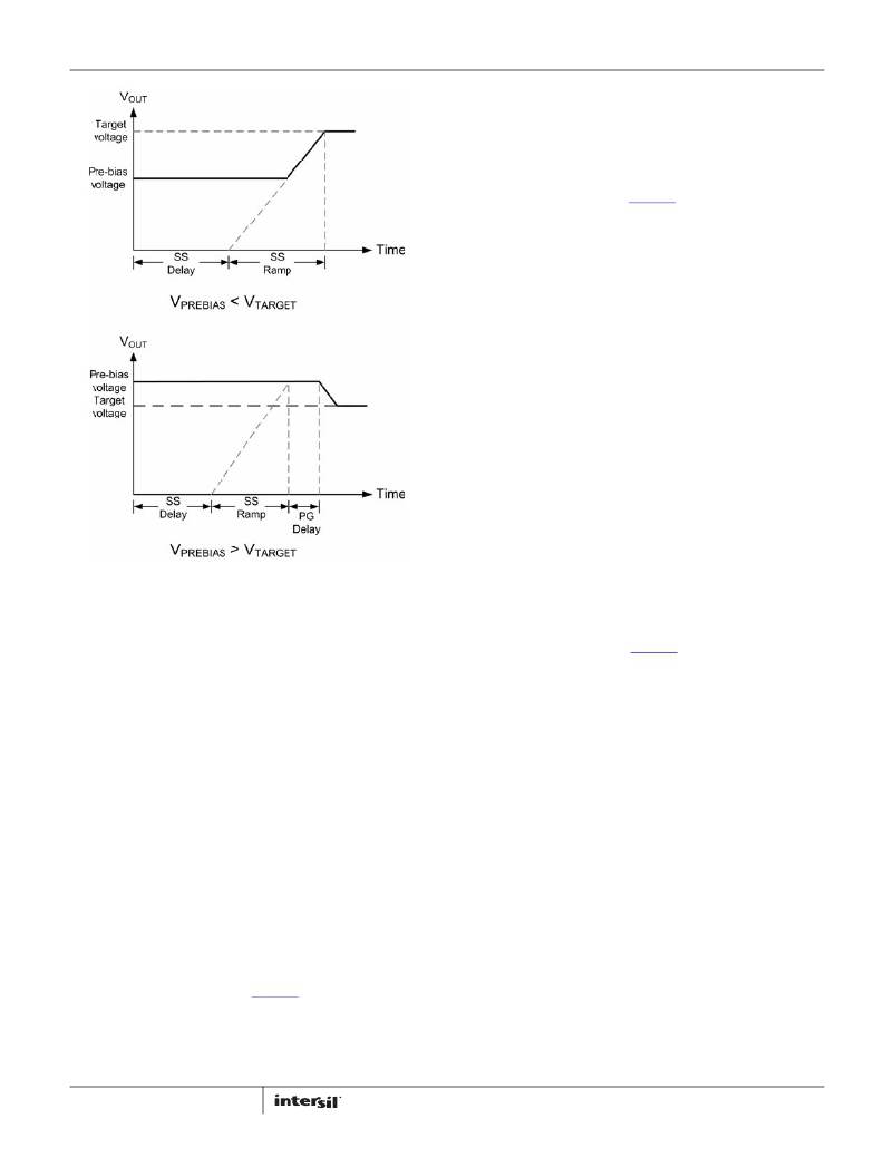
�FIGURE� 14.� OUTPUT� RESPONSES� TO� PRE-BIAS� VOLTAGES�
�Output� Overcurrent� Protection�
�The� ZL6105� can� protect� the� power� supply� from� damage� if� the�
�output� is� shorted� to� ground� or� if� an� overload� condition� is� imposed�
�on� the� output.� Once� the� current� limit� threshold� has� been� selected�
�(see� “Current� Limit� Threshold� Selection”� on� page� 19),� the� user�
�may� determine� the� desired� course� of� action� in� response� to� the�
�fault� condition.� The� following� overcurrent� protection� response�
�options� are� available:�
�1.� Initiate� a� shutdown� and� attempt� to� restart� an� infinite� number�
�of� times� with� a� preset� delay� period� between� attempts.�
�2.� Initiate� a� shutdown� and� attempt� to� restart� a� preset� number� of�
�times� with� a� preset� delay� period� between� attempts.�
�3.� Continue� operating� for� a� given� delay� period,� followed� by�
�shutdown� if� the� fault� still� exists.�
�4.� Continue� operating� through� the� fault� (this� could� result� in�
�permanent� damage� to� the� power� supply).�
�5.� Initiate� an� immediate� shutdown.�
�The� default� response� from� an� overcurrent� fault� is� an� immediate�
�shutdown� of� the� device.� The� device� will� continuously� check� for�
�the� presence� of� the� fault� condition,� and� if� the� fault� condition� no�
�longer� exists� the� device� will� be� re-enabled.�
�Please� refer� to� Application� Note� AN2033� for� details� on� how� to�
�select� specific� overcurrent� fault� response� options� via� I� 2� C/SMBus.�
�24�
�The� default� response� from� a� temperature� fault� is� an� immediate�
�shutdown� of� the� device.� The� device� will� continuously� check� for�
�the� fault� condition,� and� once� the� fault� has� cleared� the� ZL6105�
�will� be� re-enabled.�
�Please� refer� to� Application� Note� AN2033� for� details� on� how� to� select�
�specific� temperature� fault� response� options� via� I� 2� C/SMBus.�
�Voltage� Tracking�
�Numerous� high� performance� systems� place� stringent� demands�
�on� the� order� in� which� the� power� supply� voltages� are� turned� on.�
�This� is� particularly� true� when� powering� FPGAs,� ASICs,� and� other�
�advanced� processor� devices� that� require� multiple� supply� voltages�
�to� power� a� single� die.� In� most� cases,� the� I/O� interface� operates� at�
�a� higher� voltage� than� the� core� and� therefore� the� core� supply�
�voltage� must� not� exceed� the� I/O� supply� voltage� according� to� the�
�manufacturers'� specifications.�
�Voltage� tracking� protects� these� sensitive� ICs� by� limiting� the�
�differential� voltage� between� multiple� power� supplies� during� the�
�power-up� and� power� down� sequence.� The� ZL6105� integrates� a�
�lossless� tracking� scheme� that� allows� its� output� to� track� a� voltage�
�that� is� applied� to� the� VTRK� pin� with� no� external� components�
�required.� The� VTRK� pin� is� an� analog� input� that,� when� tracking�
�mode� is� enabled,� configures� the� voltage� applied� to� the� VTRK� pin�
�to� act� as� a� reference� for� the� device’s� output� regulation.�
�The� ZL6105� offers� two� modes� of� tracking� as� follows:�
�1.� Coincident� .� This� mode� configures� the� ZL6105� to� ramp� its�
�output� voltage� at� the� same� rate� as� the� voltage� applied� to� the�
�VTRK� pin.�
�FN6906.5�
�December� 19,� 2013�
�相关PDF资料 |
PDF描述 |
|---|---|
| RBM18DREI | CONN EDGECARD 36POS .156 EYELET |
| B43086F2476M | 47UF 250V 16X20 SINGLE END |
| ISL6307CRZ-T | IC REG CTRLR BUCK PWM VM 48-QFN |
| ISL6401CB-T | IC REG CTRLR PWM CM 14-SOIC |
| GCM18DREF | CONN EDGECARD 36POS .156 EYELET |
相关代理商/技术参数 |
参数描述 |
|---|---|
| ZL6105ALAFTKR5546 | 功能描述:DC/DC 开关控制器 RoHS:否 制造商:Texas Instruments 输入电压:6 V to 100 V 开关频率: 输出电压:1.215 V to 80 V 输出电流:3.5 A 输出端数量:1 最大工作温度:+ 125 C 安装风格: 封装 / 箱体:CPAK |
| ZL6105ALAFTKR5549 | 制造商:Intersil Corporation 功能描述:ADAPTIVE DIGITAL DC-DC CONTROLLER W/ DRIVERS & I-SHARING FE0 - Tape and Reel |
| ZL6105ALAFTKR5553 | 制造商:Intersil Corporation 功能描述:ADAPTIVE DIGITAL DC-DC CONTROLLER W/ DRIVERS & I-SHARING MOD - Tape and Reel |
| ZL6105ALAFTKR5554 | 制造商:Intersil Corporation 功能描述:ADAPTIVE DIGITAL DC-DC CONTROLLER W/ DRIVERS & I-SHARING MOD - Tape and Reel |
| ZL6105ALAFTR5546 | 功能描述:IC REG CTRLR BUCK PWM VM 36-QFN RoHS:是 类别:集成电路 (IC) >> PMIC - 稳压器 - DC DC 切换控制器 系列:- 产品培训模块:Lead (SnPb) Finish for COTS Obsolescence Mitigation Program 标准包装:2,500 系列:- PWM 型:电流模式 输出数:1 频率 - 最大:275kHz 占空比:50% 电源电压:18 V ~ 110 V 降压:无 升压:无 回扫:无 反相:无 倍增器:无 除法器:无 Cuk:无 隔离:是 工作温度:-40°C ~ 85°C 封装/外壳:8-SOIC(0.154",3.90mm 宽) 包装:带卷 (TR) |
发布紧急采购,3分钟左右您将得到回复。