- 您现在的位置:买卖IC网 > PDF目录1908 > COP8CCR9KMT8 (National Semiconductor)IC MCU EEPROM 8BIT 32K 56-TSSOP PDF资料下载
参数资料
| 型号: | COP8CCR9KMT8 |
| 厂商: | National Semiconductor |
| 文件页数: | 60/111页 |
| 文件大小: | 0K |
| 描述: | IC MCU EEPROM 8BIT 32K 56-TSSOP |
| 标准包装: | 34 |
| 系列: | COP8™ 8C |
| 核心处理器: | COP8 |
| 芯体尺寸: | 8-位 |
| 速度: | 20MHz |
| 连通性: | Microwire/Plus(SPI),UART/USART |
| 外围设备: | 欠压检测/复位,POR,PWM,WDT |
| 输入/输出数: | 49 |
| 程序存储器容量: | 32KB(32K x 8) |
| 程序存储器类型: | 闪存 |
| RAM 容量: | 1K x 8 |
| 电压 - 电源 (Vcc/Vdd): | 2.7 V ~ 5.5 V |
| 数据转换器: | A/D 16x10b |
| 振荡器型: | 内部 |
| 工作温度: | -40°C ~ 85°C |
| 封装/外壳: | 56-TFSOP(0.240",6.10mm 宽) |
| 包装: | 管件 |
| 其它名称: | *COP8CCR9KMT8 |
第1页第2页第3页第4页第5页第6页第7页第8页第9页第10页第11页第12页第13页第14页第15页第16页第17页第18页第19页第20页第21页第22页第23页第24页第25页第26页第27页第28页第29页第30页第31页第32页第33页第34页第35页第36页第37页第38页第39页第40页第41页第42页第43页第44页第45页第46页第47页第48页第49页第50页第51页第52页第53页第54页第55页第56页第57页第58页第59页当前第60页第61页第62页第63页第64页第65页第66页第67页第68页第69页第70页第71页第72页第73页第74页第75页第76页第77页第78页第79页第80页第81页第82页第83页第84页第85页第86页第87页第88页第89页第90页第91页第92页第93页第94页第95页第96页第97页第98页第99页第100页第101页第102页第103页第104页第105页第106页第107页第108页第109页第110页第111页
SNOS535I – OCTOBER 2000 – REVISED MARCH 2013
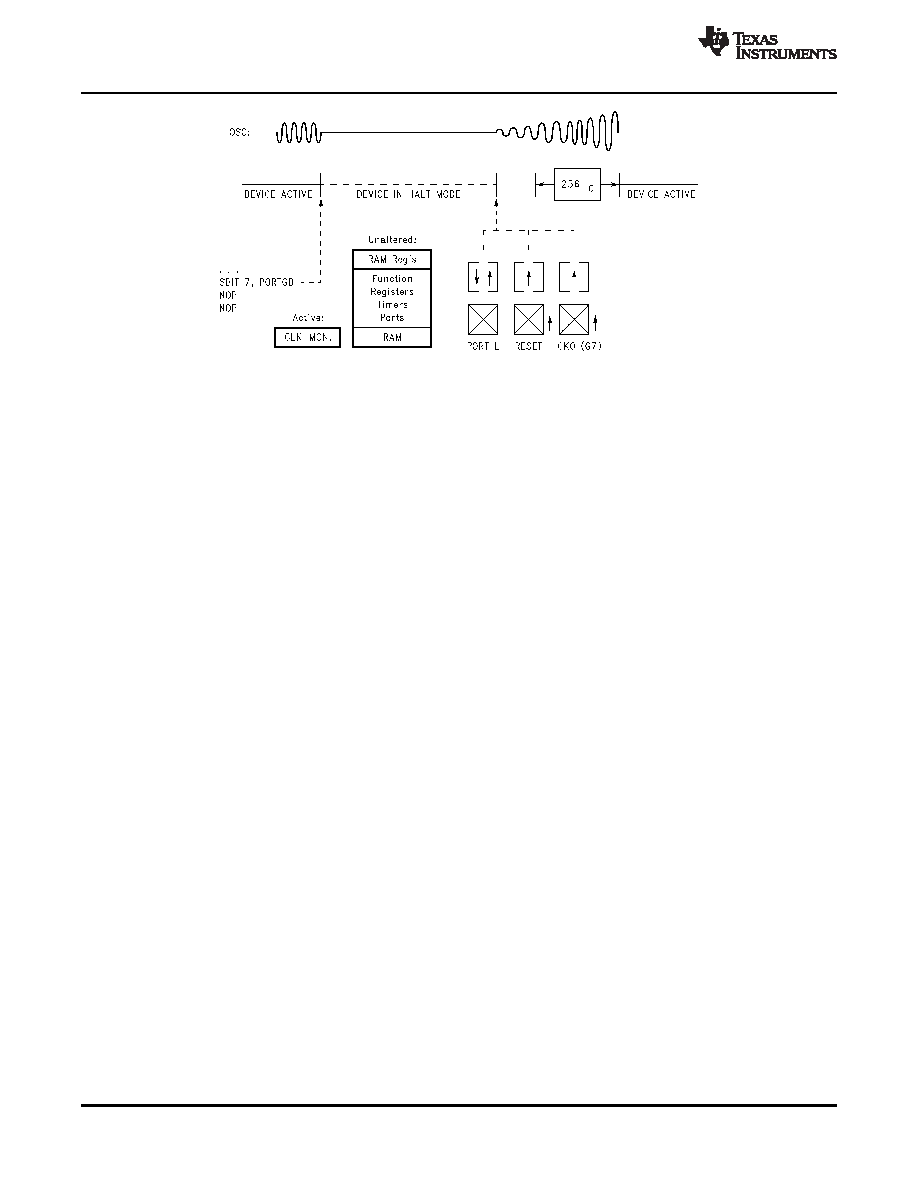
Figure 5-14. Wake-up from HALT
5.12.3.2 High Speed Idle Mode
In the IDLE mode, program execution stops and power consumption is reduced to a very low level as with
the HALT mode. However, the high speed oscillator, IDLE Timer (Timer T0), and Clock Monitor continue
to operate, allowing real time to be maintained. The device remains idle for a selected amount of time up
to 65,536 instruction cycles, or 32.768 milliseconds with a 2 MHz instruction clock frequency, and then
automatically exits the IDLE mode and returns to normal program execution.
The device is placed in the IDLE mode under software control by setting the IDLE bit (bit 6 of the Port G
data register).
The IDLE Timer window is selectable from one of five values, 4k, 8k, 16k, 32k or 64k instruction cycles.
Selection of this value is made through the ITMR register.
The IDLE mode uses the on-chip IDLE Timer (Timer T0) to keep track of elapsed time in the IDLE state.
The IDLE Timer runs continuously at the instruction clock rate, whether or not the device is in the IDLE
mode. Each time the bit of the timer associated with the selected window toggles, the T0PND bit is set, an
interrupt is generated (if enabled), and the device exits the IDLE mode if in that mode. If the IDLE Timer
interrupt is enabled, the interrupt is serviced before execution of the main program resumes. (However,
the instruction which was started as the part entered the IDLE mode is completed before the interrupt is
serviced. This instruction should be a NOP which should follow the enter IDLE instruction.) The user must
reset the IDLE Timer pending flag (T0PND) before entering the IDLE mode.
As with the HALT mode, this device can also be returned to normal operation with a reset, or with a Multi-
Input Wake-up input. Upon reset the ITMR register is cleared and the ITMR register selects the 4,096
instruction cycle tap of the Idle Timer.
The IDLE Timer cannot be started or stopped under software control, and it is not memory mapped, so it
cannot be read or written by the software. Its state upon Reset is unknown. Therefore, if the device is put
into the IDLE mode at an arbitrary time, it will stay in the IDLE mode for somewhere between 1 and the
selected number of instruction cycles.
In order to precisely time the duration of the IDLE state, entry into the IDLE mode must be synchronized to
the state of the IDLE Timer. The best way to do this is to use the IDLE Timer interrupt, which occurs on
every underflow of the bit of the IDLE Timer which is associated with the selected window. Another
method is to poll the state of the IDLE Timer pending bit T0PND, which is set on the same occurrence.
The Idle Timer interrupt is enabled by setting bit T0EN in the ICNTRL register.
Any time the IDLE Timer window length is changed there is the possibility of generating a spurious IDLE
Timer interrupt by setting the T0PND bit. The user is advised to disable IDLE Timer interrupts prior to
changing the value of the ITSEL bits of the ITMR Register and then clear the TOPND bit before
attempting to synchronize operation to the IDLE Timer.
52
Functional Description
Copyright 2000–2013, Texas Instruments Incorporated
相关PDF资料 |
PDF描述 |
|---|---|
| COP8SAA716M8/NOPB | IC MCU OTP 8BIT 1K 16-SOIC |
| CP2101-GMR | IC CTRLR BRIDGE USB-UART 28MLP |
| CP2103-GMR | IC CTRLR BRIDGE USB-UART 28MLP |
| CP2104-F03-GM | IC SGL USB-TO-UART BRIDGE 24QFN |
| CP2105-F01-GM | IC SGL USB-DL UART BRIDGE 24QFN |
相关代理商/技术参数 |
参数描述 |
|---|---|
| COP8CCR9LVA7 | 功能描述:8位微控制器 -MCU RoHS:否 制造商:Silicon Labs 核心:8051 处理器系列:C8051F39x 数据总线宽度:8 bit 最大时钟频率:50 MHz 程序存储器大小:16 KB 数据 RAM 大小:1 KB 片上 ADC:Yes 工作电源电压:1.8 V to 3.6 V 工作温度范围:- 40 C to + 105 C 封装 / 箱体:QFN-20 安装风格:SMD/SMT |
| COP8CCR9LVA7/63 | 制造商:Texas Instruments 功能描述: |
| COP8CCR9LVA7/63SN | 功能描述:闪存 RoHS:否 制造商:ON Semiconductor 数据总线宽度:1 bit 存储类型:Flash 存储容量:2 MB 结构:256 K x 8 定时类型: 接口类型:SPI 访问时间: 电源电压-最大:3.6 V 电源电压-最小:2.3 V 最大工作电流:15 mA 工作温度:- 40 C to + 85 C 安装风格:SMD/SMT 封装 / 箱体: 封装:Reel |
| COP8CCR9LVA7/NOPB | 功能描述:8位微控制器 -MCU RoHS:否 制造商:Silicon Labs 核心:8051 处理器系列:C8051F39x 数据总线宽度:8 bit 最大时钟频率:50 MHz 程序存储器大小:16 KB 数据 RAM 大小:1 KB 片上 ADC:Yes 工作电源电压:1.8 V to 3.6 V 工作温度范围:- 40 C to + 105 C 封装 / 箱体:QFN-20 安装风格:SMD/SMT |
| COP8CCR9LVA763SN | 制造商:National Semiconductor 功能描述:MCU 8-bit COP8 CISC 32KB Flash 5V 68-Pin PLCC |
发布紧急采购,3分钟左右您将得到回复。