- 您现在的位置:买卖IC网 > PDF目录16440 > EVAL-ADE5169EBZ-2 (Analog Devices Inc)BOARD EVALUATION FOR AD5169 PDF资料下载
参数资料
| 型号: | EVAL-ADE5169EBZ-2 |
| 厂商: | Analog Devices Inc |
| 文件页数: | 118/156页 |
| 文件大小: | 0K |
| 描述: | BOARD EVALUATION FOR AD5169 |
| 标准包装: | 1 |
| 主要目的: | 电源管理,电度表/功率表 |
| 嵌入式: | 是 |
| 已用 IC / 零件: | ADE5169 |
| 主要属性: | 用于汇编语言和 C 代码的 IAR 工具 |
| 次要属性: | 隔离和非隔离输出选项 |
| 已供物品: | 板,软件 |
第1页第2页第3页第4页第5页第6页第7页第8页第9页第10页第11页第12页第13页第14页第15页第16页第17页第18页第19页第20页第21页第22页第23页第24页第25页第26页第27页第28页第29页第30页第31页第32页第33页第34页第35页第36页第37页第38页第39页第40页第41页第42页第43页第44页第45页第46页第47页第48页第49页第50页第51页第52页第53页第54页第55页第56页第57页第58页第59页第60页第61页第62页第63页第64页第65页第66页第67页第68页第69页第70页第71页第72页第73页第74页第75页第76页第77页第78页第79页第80页第81页第82页第83页第84页第85页第86页第87页第88页第89页第90页第91页第92页第93页第94页第95页第96页第97页第98页第99页第100页第101页第102页第103页第104页第105页第106页第107页第108页第109页第110页第111页第112页第113页第114页第115页第116页第117页当前第118页第119页第120页第121页第122页第123页第124页第125页第126页第127页第128页第129页第130页第131页第132页第133页第134页第135页第136页第137页第138页第139页第140页第141页第142页第143页第144页第145页第146页第147页第148页第149页第150页第151页第152页第153页第154页第155页第156页
�� �
�
�ADE5166/ADE5169/ADE5566/ADE5569�
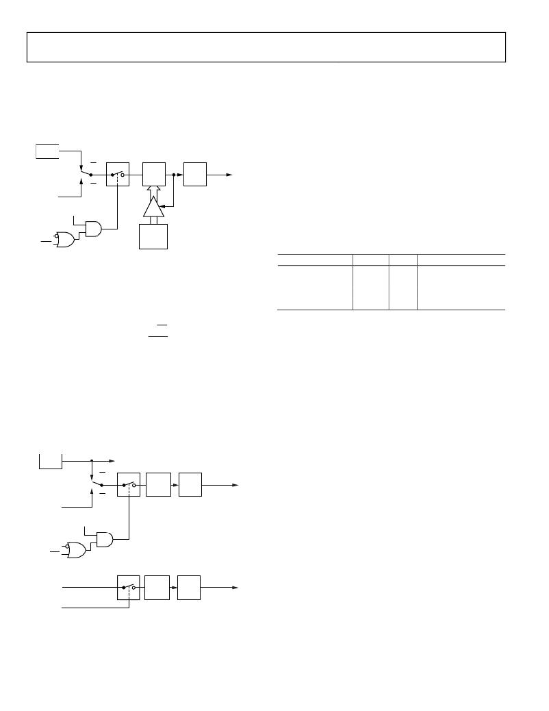
�Mode� 2� (8-Bit� Timer/Counter� with� Autoreload)�
�Mode� 2� configures� the� timer� SFR� (TH0,� Address� 0x8C)� as� an� 8-bit�
�counter� (TL0,� Address� 0x8A)� with� automatic� reload,� as� shown� in�
�Figure� 100.� Overflow� from� TL0� not� only� sets� TF0� (Address�
�0x88[5])� but� also� reloads� TL0� with� the� contents� of� TH0,� which� is�
�preset� by� software.� The� reload� leaves� TH0� unchanged.�
�Data� Sheet�
�TIMER� 2�
�Timer/Counter� 2� Data� Registers�
�Timer/Counter� 2� also� has� two� pairs� of� 8-bit� data� registers� asso-�
�ciated� with� it:� Timer� 2� high� byte� SFR� (TH2,� Address� 0xCD),�
�Timer� 2� low� byte� SFR� (TL2,� Address� 0xCC),� Timer� 2� reload/�
�capture� high� byte� SFR� (RCAP2H,� Address� 0xCB),� and� Timer� 2�
�f� CORE�
�P0.6/T0�
�TR0�
�C/T0� =� 0�
�C/T0� =� 1�
�TL0�
�(8� BITS)�
�CONTROL�
�TF0�
�INTERRUPT�
�reload/capture� low� byte� SFR� (RCAP2L,� Address� 0xCA).� These�
�SFRs� are� used� both� as� timer� data� registers� and� as� timer� capture/�
�reload� registers� (see� Table� 120� to� Table� 123).�
�Timer/Counter� 2� Operating� Modes�
�The� following� sections� describe� the� operating� modes� for� Timer/�
�Counter� 2.� The� operating� modes� are� selected� by� bits� in� the� Timer/�
�Counter� 2� control� SFR� (T2CON,� Address� 0xC8),� as� shown� in�
�GATE�
�INT0�
�RELOAD�
�TH0�
�(8� BITS)�
�Figure� 100.� Timer/Counter� 0,� Mode� 2�
�Table� 115� and� Table� 124.�
�Table� 124.� T2CON� O� perating� Modes�
�RCLK� or� TCLK� CAP2� TR2�
�Mode�
�Mode� 3� (Two� 8-Bit� Timer/Counters)�
�Mode� 3� has� different� effects� on� Timer� 0� and� Timer� 1.� Timer� 1� in�
�Mode� 3� simply� holds� its� count.� The� effect� is� the� same� as� setting�
�TR1� =� 0.� Timer� 0� in� Mode� 3� establishes� TL0� and� TH0� as� two�
�0�
�0�
�1�
�X�
�0�
�1�
�X�
�X�
�1�
�1�
�1�
�0�
�16-bit� autoreload�
�16-bit� capture�
�Baud� rate�
�Off�
�separate� counters.� This� configuration� is� shown� in� Figure� 101.�
�TL0� uses� the� Timer� 0� control� bits,� C/T0� ,� Gate0� (see� Table� 113),�
�TR0,� TF0� (see� Table� 114),� and� the� INT0� pin.� TH0� is� locked� into�
�a� timer� function� (counting� machine� cycles)� and� takes� over� the�
�use� of� TR1� and� TF1� from� Timer� 1.� Therefore,� TH0� controls� the�
�Timer� 1� interrupt.� Mode� 3� is� provided� for� applications� requiring�
�an� extra� 8-bit� timer� or� counter.�
�When� Timer� 0� is� in� Mode� 3,� Timer� 1� can� be� turned� on� and� off�
�by� switching� it� out� of� and� into� its� own� Mode� 3,� or� it� can� be� used�
�by� the� serial� interface� as� a� baud� rate� generator.� In� fact,� Timer� 1�
�can� be� used� in� any� application� not� requiring� an� interrupt� from�
�Timer� 1� itself.�
�16-Bit� Autoreload� Mode�
�The� 16-bit� autoreload� mode� has� two� options� that� are� selected� by�
�EXEN2� (Bit� 3)� in� the� Timer/Counter� 2� control� SFR� (T2CON,�
�Address� 0xC8).� If� EXEN2� =� 0� when� Timer� 2� rolls� over,� it� not� only�
�sets� TF2� but� also� causes� the� Timer� 2� SFRs� to� be� reloaded� with� the�
�16-bit� value� in� both� the� Timer� 2� reload/capture� high� byte� SFR�
�(RCAP2H,� Address� 0xCB)� and� Timer� 2� reload/capture� low� byte�
�SFR� (RCAP2L,� Address� 0xCA),� which� are� preset� by� software.� If�
�EXEN2� =� 1,� Timer� 2� performs� the� same� events� as� when� EXEN2� =� 0�
�but� adds� a� 1-to-0� transition� at� the� external� input� pin,� T2EX,� which�
�triggers� the� 16-bit� reload� and� sets� EXF2� (T2CON[6]).� Autoreload�
�mode� is� shown� in� Figure� 102.�
�f� CORE�
�CORE�
�CLK/12�
�16-Bit� Capture� Mode�
�C/T0� =� 0�
�TL0�
�(8� BITS)�
�TF0�
�INTERRUPT�
�The� 16-bit� capture� mode� has� two� options� that� are� selected� by�
�EXEN2� (Bit� 3)� in� the� Timer/Counter� 2� control� SFR� (T2CON,�
�P0.6/T0�
�C/T0� =� 1�
�Address� 0xC8).� If� EXEN2� =� 0,� Timer� 2� is� a� 16-bit� timer� or� counter�
�that,� upon� overflowing,� sets� the� Timer� 2� overflow� bit� (TF2,� Bit� 7).�
�GATE�
�INT� 0�
�TR0�
�CONTROL�
�This� bit� can� be� used� to� generate� an� interrupt.� If� EXEN2� =� 1,� then�
�Timer� 2� performs� the� same� events� as� when� EXEN2� =� 0,� but� it�
�adds� a� l-to-0� transition� on� the� T2EX� external� input,� causing� the�
�current� value� in� the� Timer� 2� SFRs,� TL2� (Address� 0xCC)� and� TH2�
�(Address� 0xCD)� to� be� captured� into� the� RCAP2L� (Address� 0xCA)�
�and� RCAP2H� (Address� 0xCB)� SFRs,� respectively.� In� addition,� the�
�f� CORE� /12�
�TH0�
�(8� BITS)�
�TF1�
�INTERRUPT�
�transition� at� T2EX� causes� the� EXF2� bit� (Bit� 6)� in� the� T2CON� SFR�
�(Address� 0xC8)� to� be� set,� and� EXF2,� like� TF2,� can� generate� an�
�TR1�
�Figure� 101.� Timer/Counter� 0,� Mode� 3�
�interrupt.� Capture� mode� is� shown� in� Figure� 103.� The� baud� rate�
�generator� mode� is� selected� by� RCLK� =� 1� and/or� TCLK� =� 1.�
�Rev.� D� |� Page� 118� of� 156�
�相关PDF资料 |
PDF描述 |
|---|---|
| VE-J1M-EX | CONVERTER MINIMOD DC/DC 10V 75W |
| VE-21M-EX | CONVERTER MOD DC/DC 10V 75W |
| VE-21R-EX | CONVERTER MOD DC/DC 7.5V 75W |
| AD9912A/PCBZ | BOARD EVALUATION FOR AD9912 |
| H1KXH-2636M | IDC CABLE - HPK26H/AE26M/X |
相关代理商/技术参数 |
参数描述 |
|---|---|
| EVAL-ADE5169F62EBZ | 制造商:Analog Devices 功能描述:EVALUATION BOARD FOR ADE5169 - Boxed Product (Development Kits) 制造商:Rochester Electronics LLC 功能描述: |
| EVAL-ADE5569F62EBZ | 制造商:AD 制造商全称:Analog Devices 功能描述:Single-Phase Energy Measurement IC with 8052 MCU, RTC, and LCD Driver |
| EVAL-ADE7169EBZ-2 | 功能描述:BOARD EVALUATION FOR ADE7169F16 RoHS:是 类别:编程器,开发系统 >> 评估演示板和套件 系列:- 标准包装:1 系列:PCI Express® (PCIe) 主要目的:接口,收发器,PCI Express 嵌入式:- 已用 IC / 零件:DS80PCI800 主要属性:- 次要属性:- 已供物品:板 |
| EVAL-ADE7169F16EB | 制造商:AD 制造商全称:Analog Devices 功能描述:Single-Phase Energy Measurement IC with 8052 MCU, RTC and LCD driver |
| EVAL-ADE7169F16EBZ | 制造商:Analog Devices 功能描述:Evaluation Board For ADE7169 制造商:Analog Devices 功能描述:EVAL BD FOR ADE7169 - Bulk |
发布紧急采购,3分钟左右您将得到回复。