- 您现在的位置:买卖IC网 > PDF目录16440 > EVAL-ADE5169EBZ-2 (Analog Devices Inc)BOARD EVALUATION FOR AD5169 PDF资料下载
参数资料
| 型号: | EVAL-ADE5169EBZ-2 |
| 厂商: | Analog Devices Inc |
| 文件页数: | 57/156页 |
| 文件大小: | 0K |
| 描述: | BOARD EVALUATION FOR AD5169 |
| 标准包装: | 1 |
| 主要目的: | 电源管理,电度表/功率表 |
| 嵌入式: | 是 |
| 已用 IC / 零件: | ADE5169 |
| 主要属性: | 用于汇编语言和 C 代码的 IAR 工具 |
| 次要属性: | 隔离和非隔离输出选项 |
| 已供物品: | 板,软件 |
第1页第2页第3页第4页第5页第6页第7页第8页第9页第10页第11页第12页第13页第14页第15页第16页第17页第18页第19页第20页第21页第22页第23页第24页第25页第26页第27页第28页第29页第30页第31页第32页第33页第34页第35页第36页第37页第38页第39页第40页第41页第42页第43页第44页第45页第46页第47页第48页第49页第50页第51页第52页第53页第54页第55页第56页当前第57页第58页第59页第60页第61页第62页第63页第64页第65页第66页第67页第68页第69页第70页第71页第72页第73页第74页第75页第76页第77页第78页第79页第80页第81页第82页第83页第84页第85页第86页第87页第88页第89页第90页第91页第92页第93页第94页第95页第96页第97页第98页第99页第100页第101页第102页第103页第104页第105页第106页第107页第108页第109页第110页第111页第112页第113页第114页第115页第116页第117页第118页第119页第120页第121页第122页第123页第124页第125页第126页第127页第128页第129页第130页第131页第132页第133页第134页第135页第136页第137页第138页第139页第140页第141页第142页第143页第144页第145页第146页第147页第148页第149页第150页第151页第152页第153页第154页第155页第156页
�� �
�
�Data� Sheet�
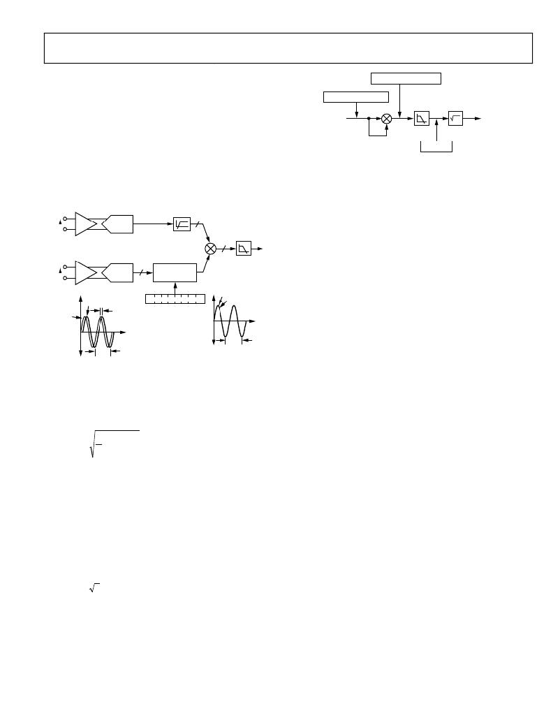
�Figure� 59� illustrates� how� the� phase� compensation� is� used� to�
�ADE5166/ADE5169/ADE5566/ADE5569�
�I� 2� (t� )� =� I� 2� –� I� 2� cos� (2ω� t� )�
�remove� a� 0.1°� phase� lead� in� the� current� channel� due� to� the�
�external� transducer.� To� cancel� the� lead� (0.1°)� in� the� current�
�channel,� a� phase� lead� must� also� be� introduced� into� the� voltage�
�channel.� The� resolution� of� the� phase� adjustment� allows� the� intro-�
�I(t� )� =� √2� ×� I� sin(ω� t� )�
�INPUT�
�LPF3�
�IRMS�
�duction� of� a� phase� lead� in� increments� of� 0.026°.� The� phase� lead� is�
�I�
�achieved� by� introducing� a� time� advance� into� the� voltage� channel.�
�A� time� advance� of� 4.88� μs� is� made� by� writing� ?4� (0x3C)� to� the�
�time� delay� block,� thus� reducing� the� amount� of� time� delay� by�
�4.88� μs,� or� equivalently,� a� phase� lead� of� approximately� 0.1°� at� a�
�line� frequency� of� 60� Hz� (0x3C� represents� ?4� because� the� register�
�is� centered� with� 0� at� 0x40).�
�I� P� /I� PA� HPF�
�24�
�PGA1� ADC� 1�
�I� N� LPF2�
�24�
�I� 2� (t� )� =� I� 2�
�Figure� 60.� IRMS� Signal� Processing�
�The� I� rms� signal� can� be� read� from� the� waveform� register� by� set-�
�ting� the� WAVMODE� register� (Address� 0x0D)� and� setting� the�
�WFSM� bit� (Bit� 5)� in� the� Interrupt� Enable� 3� SFR� (MIRQENH,�
�Address� 0xDB).� Like� the� current� and� voltage� channels� waveform�
�sampling� modes,� the� waveform� data� is� available� at� sample� rates� of�
�25.6� kSPS,� 12.8� kSPS,� 6.4� kSPS,� and� 3.2� kSPS.�
�It� is� important� to� note� that� when� the� current� input� is� larger� than�
�V�
�V� P�
�V� N�
�PGA2�
�ADC� 2�
�1�
�7�
�DELAY� BLOCK�
�1.22μs/LSB�
�0�
�CHANNEL� 2� DELAY�
�REDUCED� BY� 4.88μs�
�(0.1°LEAD� AT� 60Hz)�
�0x3C� IN� PHCAL[7:0]�
�V�
�40%� of� full� scale,� the� I� rms� waveform� sample� register� does� not�
�represent� the� true� processed� rms� value.� The� rms� value� processed�
�with� this� level� of� input� is� larger� than� the� 24-bit� read� by� the� wave-�
�form� register,� making� the� value� read� truncated� on� the� high� end.�
�I�
�V�
�0.1°�
�1� 0� 0� 1� 0� 1� 1� 1�
�PHCAL[7:0]�
�–231.93μs� TO� +48.83μs�
�I�
�Figure� 61� and� Figure� 62� show� the� detail� of� the� signal� processsing�
�chain� for� the� rms� calculation� on� the� current� channel.� The� current�
�channel� rms� value� is� processed� from� the� samples� used� in� the�
�60Hz�
�Figure� 59.� Phase� Calibration�
�RMS� CALCULATION�
�60Hz�
�current� channel� waveform� sampling� mode� and� is� stored� in� the�
�unsigned,� 24-bit� IRMS� SFRs� (IRMSL,� Address� 0xD4;� IRMSM,�
�Address� 0xD5;� and� IRMSH,� Address� 0xD6).� One� LSB� of� the�
�current� channel� rms� register� (IRMSL,� IRMSM,� and� IRMSH)� is�
�equivalent� to� 1� LSB� of� a� current� channel� waveform� sample.�
�×� ∫� I� 2� (� t� )� dt�
�1�
�(1)�
�T�
�Current� Channel� RMS� Calculation�
�The� root� mean� square� (rms)� value� of� a� continuous� signal,� I(t),� is�
�defined� as�
�T�
�I� rms� =�
�0�
�For� time� sampling� signals,� rms� calculation� involves� squaring� the�
�signal,� taking� the� average,� and� obtaining� the� square� root.� The�
�ADE5166/ADE5169/ADE5566/ADE5569� implement� this� method�
�on� the� current� channel� by� serially� squaring� the� input,� averaging�
�the� results,� and� then� taking� the� square� root� of� the� average.� The�
�averaging� part� of� this� signal� processing� is� done� by�
�implementing� a� low-pass� filter� (LPF3� in� Figure� 60,� Figure� 61�
�and� Figure� 62).�
�The� update� rate� of� the� current� channel� rms� measurement� is�
�4.096� MHz/5.� To� minimize� noise� in� the� reading� of� the� register,� the�
�I� rms� register� can� also� be� configured� to� update� only� with� the� zero�
�crossing� of� the� voltage� input.� This� configuration� is� done� by� setting�
�the� ZXRMS� bit� (Bit� 2)� in� the� MODE2� register� (Address� 0x0C).�
�With� the� different� specified� full-scale� analog� input� values,� the� ADC�
�produces� an� output� code� that� is� approximately� ±0d2,684,354�
�(see� the� Current� Channel� ADC� section).� Similarly,� the� equiva-�
�lent� rms� value� of� a� full-scale� ac� signal� is� 0d1,898,124� (0x1CF68C).�
�The� current� rms� measurement� provided� in� the� ADE5166/�
�ADE5169/ADE5566/ADE5569� is� accurate� to� within� ±0.5%�
�for� signal� inputs� between� full� scale� and� full� scale/500.� The�
�conversion� from� the� register� value� to� amps� must� be� done�
�externally� in� the� microprocessor� using� an� amps/LSB� constant.�
�This� LPF� has� a� ?3� dB� cutoff� frequency� of� 2� Hz� when� MCLK� =�
�4.096� MHz.�
�I� (� t� )� =� 2� ×� I� sin(� ω� t� )�
�where� V� is� the� rms� voltage.�
�I� 2� (� t� )� =� I� 2� ?� I� 2� cos� (� 2� ω� t� )�
�(2)�
�(3)�
�Current� Channel� RMS� Offset� Compensation�
�The� ADE5166/ADE5169/ADE5566/ADE5569� incorporate� a� cur-�
�rent� channel� rms� offset� compensation� register� (IRMSOS).� This� is�
�a� 12-bit,� signed� register� that� can� be� used� to� remove� offset� in� the�
�current� channel� rms� calculation.� An� offset� can� exist� in� the� rms�
�calculation� due� to� input� noises� that� are� integrated� into� the� dc�
�When� this� signal� goes� through� LPF3,� the� cos(2ωt)� term� is� atte-�
�component� of� V� 2� (t).�
�nuated� and� only� the� dc� term,� I� rms2� (shown� as� I� 2� in� Figure� 60),�
�goes� through.�
�Rev.� D� |� Page� 57� of� 156�
�相关PDF资料 |
PDF描述 |
|---|---|
| VE-J1M-EX | CONVERTER MINIMOD DC/DC 10V 75W |
| VE-21M-EX | CONVERTER MOD DC/DC 10V 75W |
| VE-21R-EX | CONVERTER MOD DC/DC 7.5V 75W |
| AD9912A/PCBZ | BOARD EVALUATION FOR AD9912 |
| H1KXH-2636M | IDC CABLE - HPK26H/AE26M/X |
相关代理商/技术参数 |
参数描述 |
|---|---|
| EVAL-ADE5169F62EBZ | 制造商:Analog Devices 功能描述:EVALUATION BOARD FOR ADE5169 - Boxed Product (Development Kits) 制造商:Rochester Electronics LLC 功能描述: |
| EVAL-ADE5569F62EBZ | 制造商:AD 制造商全称:Analog Devices 功能描述:Single-Phase Energy Measurement IC with 8052 MCU, RTC, and LCD Driver |
| EVAL-ADE7169EBZ-2 | 功能描述:BOARD EVALUATION FOR ADE7169F16 RoHS:是 类别:编程器,开发系统 >> 评估演示板和套件 系列:- 标准包装:1 系列:PCI Express® (PCIe) 主要目的:接口,收发器,PCI Express 嵌入式:- 已用 IC / 零件:DS80PCI800 主要属性:- 次要属性:- 已供物品:板 |
| EVAL-ADE7169F16EB | 制造商:AD 制造商全称:Analog Devices 功能描述:Single-Phase Energy Measurement IC with 8052 MCU, RTC and LCD driver |
| EVAL-ADE7169F16EBZ | 制造商:Analog Devices 功能描述:Evaluation Board For ADE7169 制造商:Analog Devices 功能描述:EVAL BD FOR ADE7169 - Bulk |
发布紧急采购,3分钟左右您将得到回复。