- 您现在的位置:买卖IC网 > PDF目录9984 > ICS1893AFLFT (IDT, Integrated Device Technology Inc)PHYCEIVER LOW PWR 3.3V 48-SSOP PDF资料下载
参数资料
| 型号: | ICS1893AFLFT |
| 厂商: | IDT, Integrated Device Technology Inc |
| 文件页数: | 85/136页 |
| 文件大小: | 0K |
| 描述: | PHYCEIVER LOW PWR 3.3V 48-SSOP |
| 标准包装: | 1,000 |
| 系列: | PHYceiver™ |
| 类型: | PHY 收发器 |
| 规程: | MII |
| 电源电压: | 3.14 V ~ 3.47 V |
| 安装类型: | 表面贴装 |
| 封装/外壳: | 48-BSSOP(0.295",7.50mm 宽) |
| 供应商设备封装: | 48-SSOP |
| 包装: | 带卷 (TR) |
| 其它名称: | 1893AFLFT |
第1页第2页第3页第4页第5页第6页第7页第8页第9页第10页第11页第12页第13页第14页第15页第16页第17页第18页第19页第20页第21页第22页第23页第24页第25页第26页第27页第28页第29页第30页第31页第32页第33页第34页第35页第36页第37页第38页第39页第40页第41页第42页第43页第44页第45页第46页第47页第48页第49页第50页第51页第52页第53页第54页第55页第56页第57页第58页第59页第60页第61页第62页第63页第64页第65页第66页第67页第68页第69页第70页第71页第72页第73页第74页第75页第76页第77页第78页第79页第80页第81页第82页第83页第84页当前第85页第86页第87页第88页第89页第90页第91页第92页第93页第94页第95页第96页第97页第98页第99页第100页第101页第102页第103页第104页第105页第106页第107页第108页第109页第110页第111页第112页第113页第114页第115页第116页第117页第118页第119页第120页第121页第122页第123页第124页第125页第126页第127页第128页第129页第130页第131页第132页第133页第134页第135页第136页
ICS1893AF, Rev D 10/26/04
October, 2004
52
Chapter 7
Functional Blocks
ICS1893AF Data Sheet - Release
Copyright 2004, Integrated Circuit Systems, Inc.
All rights reserved.
7.6
Functional Block: Management Interface
As part of the MAC/Repeater Interface, the ICS1893AF provides a two-wire serial management interface
which complies with the ISO/IEC 8802-3 standard MII Serial Management Interface. This interface is used
to exchange control, status, and configuration information between a Station Management entity (STA) and
the physical layer device (PHY). The PHY and STA exchange this data through a pre-defined set of
management registers. The ISO/IEC standard specifies the following components of this serial
management interface:
A set of registers (Section 7.6.1, “Management Register Set Summary”)
The frame structure (Section 7.6.2, “Management Frame Structure”)
The protocol
In compliance with the ISO/IEC specification, the ICS1893AF implementation of the serial management
interface provides a bi-directional data pin (MDIO) along with a clock (MDC) for synchronizing the
exchange of data. These pins remain active in all ICS1893AF MAC/Repeater Interface modes (that is, the
10/100 MII, 100M Symbol, and 10M Serial interface modes).
7.6.1
Management Register Set Summary
The ICS1893AF implements a Management Register set that adheres to the ISO/IEC standard. This
register set (discussed in detail in Chapter 8, “Management Register Set”) includes the mandatory ‘Basic’
Control and Status registers and the ISO/IEC ‘Extended’ registers as well as some ICS-specific registers.
7.6.2
Management Frame Structure
The Serial Management Interface is a synchronous, bi-directional, two-wire, serial interface for the
exchange of configuration, control, and status data between a PHY, such as an ICS1893AF, and an STA.
All data transferred on an MDIO signal is synchronized by its MDC signal. The PHY and STA exchange
data through a pre-defined register set.
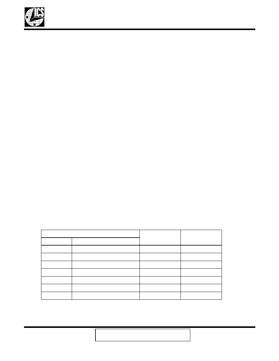
The ICS1893AF complies with the ISO/IEC defined Management Frame Structure and protocol. This
structure supports both read and write operations. Table 7-2 summarizes the Management Frame
Structure.
Note:
The Management Frame Structure starts from and returns to an IDLE condition. However, the IDLE
periods are not part of the Management Frame Structure.
Table 7-2.
Management Frame Structure Summary
Frame Field
Data
Comment
Acronym
Frame Function
PRE
Preamble (Bit 1.6)
11..11
32 ones
SFD
Start of Frame
01
2 bits
OP
Operation Code
10/01 (read/write)
2 bits
PHYAD
PHY Address (Bits 16.10:6)
AAAAA
5 bits
REGAD
Register Address
RRRRR
5 bits
TA
Turnaround
Z0/10 (read/write)
2 bits
DATA
Data
DDD..DD
16 bits
相关PDF资料 |
PDF描述 |
|---|---|
| IDT723641L20PF8 | IC FIFO SYNC 1024X36 120-TQFP |
| IDT723631L20PQF | IC FIFO SYNC 512X36 132-PQFP |
| ICS1893BFLFT | PHYCEIVER LOW PWR 3.3V 48-SSOP |
| IDT723631L20PF | IC FIFO SYNC 512X36 120-TQFP |
| VE-26F-IW-F2 | CONVERTER MOD DC/DC 72V 100W |
相关代理商/技术参数 |
参数描述 |
|---|---|
| ICS1893AFT | 功能描述:PHYCEIVER LOW PWR 3.3V 48-SSOP RoHS:否 类别:集成电路 (IC) >> 接口 - 驱动器,接收器,收发器 系列:PHYceiver™ 标准包装:1,000 系列:- 类型:收发器 驱动器/接收器数:2/2 规程:RS232 电源电压:3 V ~ 5.5 V 安装类型:表面贴装 封装/外壳:16-SOIC(0.295",7.50mm 宽) 供应商设备封装:16-SOIC 包装:带卷 (TR) |
| ICS1893AG | 制造商:ICS 制造商全称:ICS 功能描述:3.3 V 10Base-T/100Base-TX Integrated PHYceiver-TM |
| ICS1893AGI | 制造商:ICS 制造商全称:ICS 功能描述:3.3 V 10Base-T/100Base-TX Integrated PHYceiver-TM |
| ICS1893AGILF | 制造商:ICS 制造商全称:ICS 功能描述:3.3 V 10Base-T/100Base-TX Integrated PHYceiver-TM |
| ICS1893AGLF | 制造商:ICS 制造商全称:ICS 功能描述:3.3 V 10Base-T/100Base-TX Integrated PHYceiver-TM |
发布紧急采购,3分钟左右您将得到回复。