- 您现在的位置:买卖IC网 > PDF目录98145 > ST7267C8T1/XXX (STMICROELECTRONICS) 16-BIT, MROM, 30 MHz, RISC MICROCONTROLLER, PQFP48 PDF资料下载
参数资料
| 型号: | ST7267C8T1/XXX |
| 厂商: | STMICROELECTRONICS |
| 元件分类: | 微控制器/微处理器 |
| 英文描述: | 16-BIT, MROM, 30 MHz, RISC MICROCONTROLLER, PQFP48 |
| 封装: | 7 X 7 MM, LEAD FREE, TQFP-48 |
| 文件页数: | 52/189页 |
| 文件大小: | 1643K |
| 代理商: | ST7267C8T1/XXX |
第1页第2页第3页第4页第5页第6页第7页第8页第9页第10页第11页第12页第13页第14页第15页第16页第17页第18页第19页第20页第21页第22页第23页第24页第25页第26页第27页第28页第29页第30页第31页第32页第33页第34页第35页第36页第37页第38页第39页第40页第41页第42页第43页第44页第45页第46页第47页第48页第49页第50页第51页当前第52页第53页第54页第55页第56页第57页第58页第59页第60页第61页第62页第63页第64页第65页第66页第67页第68页第69页第70页第71页第72页第73页第74页第75页第76页第77页第78页第79页第80页第81页第82页第83页第84页第85页第86页第87页第88页第89页第90页第91页第92页第93页第94页第95页第96页第97页第98页第99页第100页第101页第102页第103页第104页第105页第106页第107页第108页第109页第110页第111页第112页第113页第114页第115页第116页第117页第118页第119页第120页第121页第122页第123页第124页第125页第126页第127页第128页第129页第130页第131页第132页第133页第134页第135页第136页第137页第138页第139页第140页第141页第142页第143页第144页第145页第146页第147页第148页第149页第150页第151页第152页第153页第154页第155页第156页第157页第158页第159页第160页第161页第162页第163页第164页第165页第166页第167页第168页第169页第170页第171页第172页第173页第174页第175页第176页第177页第178页第179页第180页第181页第182页第183页第184页第185页第186页第187页第188页第189页
ST7267C8 ST7267R8
145/189
MSCI PARALLEL INTERFACE (Cont’d)
17.4 MSCI PARALLEL INTERFACE CONFIGURATION EXAMPLES
17.4.1 Examples for output mode
Once the parallel interface is configured and start-
ed, the communication begins as soon as one
communication buffer is full. If the double buffer is
filled by the MSCI software (through the FIFO)
faster than the data is sent to the I/Os, the commu-
nication will be continuous during the complete
packet. If the buffer becomes empty during a com-
munication, inactive states will be inserted to wait
until the buffer is ready. During these inactive
states, the data port is not driven by the parallel in-
terface, the control lines are frozen at the CLDV
level (Control Lines Default Value).
In output mode, data is always output at the begin-
ning of the control signal cycle whatever the con-
trol signal is. The control signal must be configured
in order to match targeted device protocol.
The Control Line Default Value (CLDV) parameter
is specific and must be configured before others
control signals parameter and before enabling any
Control Signal output with the CSE bits of the
PCR2 register.
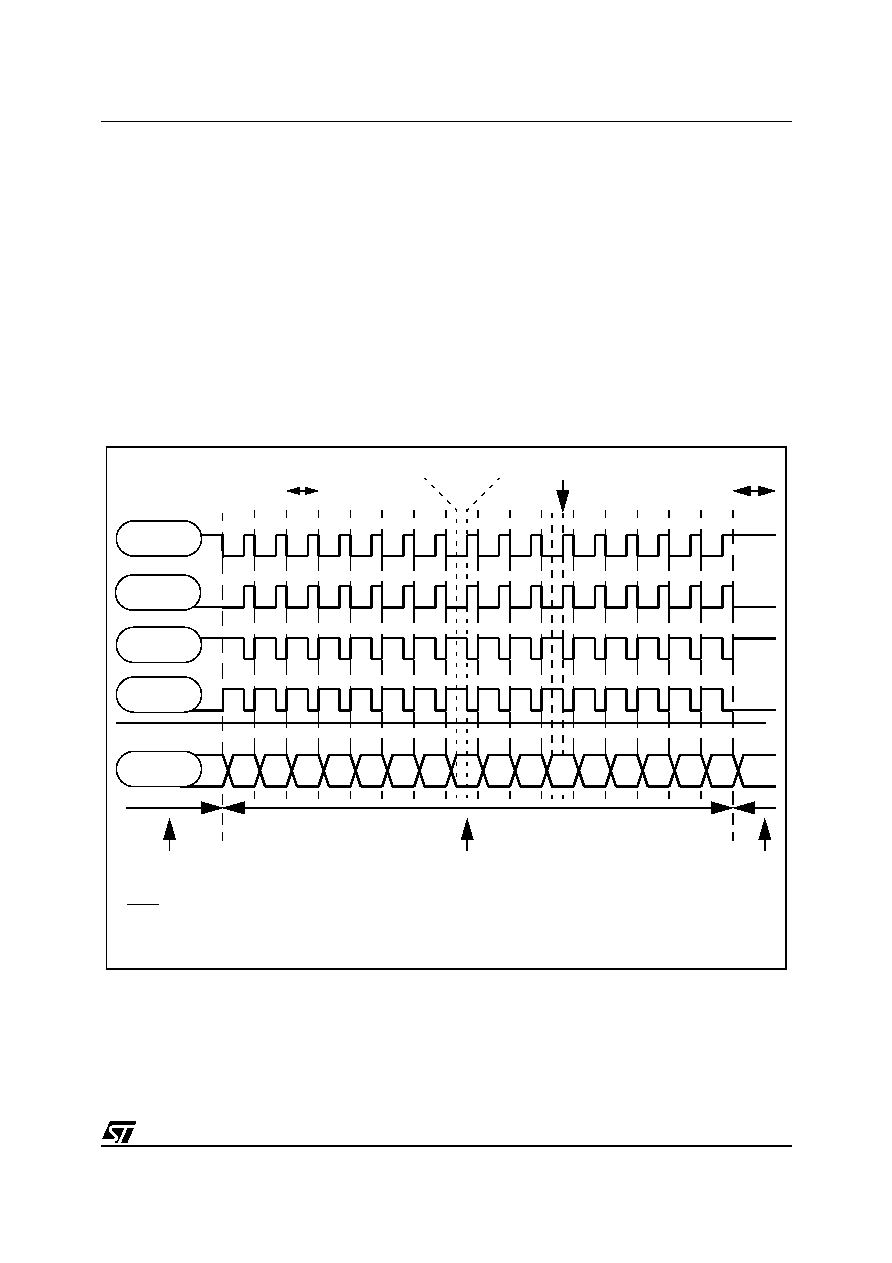
Figure 61. Examples: output mode with F=010; CSS=010
Frequency=20MHz;
Duty Cycle=33%
waiting for Buffer
full again
control signal edge 2 periods after the
beginning of the control cycle
60MHz base period
D0
D1
D2
D3
D4
D5
D6
D7
D8
D9
D10
D11
D12
D13
D14
D15
CLDV=1
CP=1
CLDV=0
CP=1
CLDV=1
CP=0
CLDV=0
CP=0
Data output
Control signal port
DATA ports
Data ports selected (depending on the mode) controlled by parallel interface
data ports controlled
by MSCI I/O Controller
data ports controlled
by MSCI I/O Controlle
Note: In output mode, short spikes can be generated on data ports before data is stable (shorter.
than the data output delay).
.
Only the Control line signals are guaranteed to be spike free signals (mandatory for
synchronous communication).
相关PDF资料 |
PDF描述 |
|---|---|
| ST72774S9T1/XXX | 8-BIT, MROM, 8 MHz, MICROCONTROLLER, PQFP44 |
| ST72E734J6D0 | 8-BIT, UVPROM, 8 MHz, MICROCONTROLLER, CDIP42 |
| ST72T774S9T1 | 8-BIT, OTPROM, 8 MHz, MICROCONTROLLER, PQFP44 |
| ST7294C6B6 | 8-BIT, MROM, 4 MHz, MICROCONTROLLER, PDIP28 |
| ST72T94C6M6 | 8-BIT, OTPROM, MICROCONTROLLER, PDSO28 |
相关代理商/技术参数 |
参数描述 |
|---|---|
| ST72681/R12 | 制造商:STMicroelectronics 功能描述:CONTROLLER FOR HIGH-PERFORMANCE BUS-POWERED USB 2.0 FLASH DR - Trays |
| ST72681/S13 | 制造商:STMicroelectronics 功能描述:CONTROLLER FOR HIGH-PERFORMANCE - Trays |
| ST7271 | 制造商:Panasonic Industrial Company 功能描述:IC |
| ST7271N5B1-CLF | 制造商:STMicroelectronics 功能描述: |
| ST727X4-EMU2B | 制造商:STMicroelectronics 功能描述:REALTIME EMULATOR BOARD - Bulk |
发布紧急采购,3分钟左右您将得到回复。