- 您现在的位置:买卖IC网 > PDF目录98145 > ST72E85A5G0 (STMICROELECTRONICS) 8-BIT, UVPROM, 4.332 MHz, MICROCONTROLLER, CQFP80 PDF资料下载
参数资料
| 型号: | ST72E85A5G0 |
| 厂商: | STMICROELECTRONICS |
| 元件分类: | 微控制器/微处理器 |
| 英文描述: | 8-BIT, UVPROM, 4.332 MHz, MICROCONTROLLER, CQFP80 |
| 封装: | WINDOWED, CERAMIC, QFP- 80 |
| 文件页数: | 90/117页 |
| 文件大小: | 748K |
| 代理商: | ST72E85A5G0 |
第1页第2页第3页第4页第5页第6页第7页第8页第9页第10页第11页第12页第13页第14页第15页第16页第17页第18页第19页第20页第21页第22页第23页第24页第25页第26页第27页第28页第29页第30页第31页第32页第33页第34页第35页第36页第37页第38页第39页第40页第41页第42页第43页第44页第45页第46页第47页第48页第49页第50页第51页第52页第53页第54页第55页第56页第57页第58页第59页第60页第61页第62页第63页第64页第65页第66页第67页第68页第69页第70页第71页第72页第73页第74页第75页第76页第77页第78页第79页第80页第81页第82页第83页第84页第85页第86页第87页第88页第89页当前第90页第91页第92页第93页第94页第95页第96页第97页第98页第99页第100页第101页第102页第103页第104页第105页第106页第107页第108页第109页第110页第111页第112页第113页第114页第115页第116页第117页
74/117
ST7285C
RDS G.B.S. (Cont’d)
4.9.3 Functional Description
4.9.3.1 Principles of Baseband Coding
Figure 34 illustrates the principles of baseband
coding. The largest element in the structure is
called a “group”. Each group contains 4 blocks of
26 bits each. Each block contains an information
word (16 bits) and a check-word (10bits).
The basic baseband data rate e is 1187.5 bits/s.
The baseband is a modified shortened cyclic code,
that means the transmitted vector c(x) is given by:
c(x) = d(x) +m(x)
*x
10 + {m(x)
*x
10}/d(x) |
mod g(x)
where, m(x) represents the 16-bit message vector:
m(x) = m
15*x
15 +m
14*x
14 +...+ m
1*x
1 +m
0*x
0
g(x) represents the polynomial generator:
g(x) = x
10 +x8 +x7 +x5 +x4 +x3 +1
and d(x) represents the offset word according to
the values tabulated in Table 9 below.
For more information about the theory and imple-
mentation of the modified shortened cyclic code,
please refer to the specification of the European
Broadcasting Union.
4.9.3.2 Hardware Configuration
The GBS circuit comprises the following functional
blocks; these are shown schematically in the Block
Diagram, Figure 35.
– 26-bit Shift Register (SR3- SR0), may act, either
as a straight 26-bit delay or as a recirculating shift
register. On each rising edge of RDSCLK a new
RDS-bit is shifted into the register. Then, the con-
tents of the shift register are rotated 26 times (one
circuit) for syndrome calculation.
In error correction mode (ECM=1), the shift reg-
ister acts only as a circular register. New RDS-bits
are not shifted in. They are stored in the parallel
shift register DR0- DR3.
– Polynomial Division circuit, comprising a 10-bit
shift register (SY0- SY1) with feedback taps for
syndrome calculation. During the rotation of the
shift register the RDS-bits are passed serially
into the polynomial division register where the
syndrome is calculated and stored.
– Syndrome Detection circuit, compares the cal-
culated syndrome with a 5(6)-word syndrome
ROM. The output consists of the block code
BL[2:0] and the VSI flag with its associated inter-
rupt. VSI is high when a valid syndrome is detect-
ed. Detection of offset syndrome, E, is enabled
by control bit US.
– 5-bit Counter (CNA), counts down on every rising
edge of RDSCLK. The counter reload register can
be written by software. On zero count, it restarts
immediately with the value of the reload register
and can generate an interrupt on zero count. This
counter is used as RDS-bit counter (26...1).
– 2-bit Counter (CNB), counts down on every zero
count of CNA. The counter can be written by soft-
ware. CNB is running free and can generate an
interrupt. This counter is used as RDS-block
counter (3...1)
– Timing Generator block comprising a modulo-
28 counter with end stops and some combina-
tional logic. The modulo-28 counter is used to
generate one shift clock, 26 rotate clocks and
one end of calculation clock. In error correction
mode (ECM=1) the shift clock is masked.
– 26-bit RDSDAT register (DR3-DR0), in parallel
to shift register SR3-SR1. It works in straight shift
mode only. On each rising edge of the RDSCLK
the RDSDAT-bit is shifted into the register. This
register is used for temporary block storage dur-
ing error correction.
– 26-bit QUALITY register (QR3-QR0), works in
straight shift mode only. On each rising edge of
the RDSCLK the QUALITY bit coming from the
demodulator is shifted into the register.
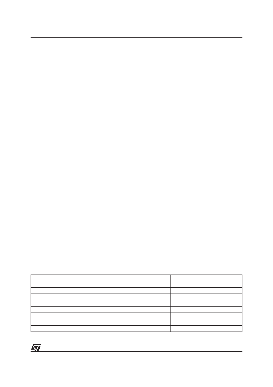
Table 9. Offset Words and their corresponding Syndromes
Offset
(block)
Block code
BL
2 BL1 BL0
Offset word
d9,d8,d7,...,d0
Syndrome
d9,d8,d7,...,d0
A
0 1 0
0011111100
1111011000
B
0 0 1
0110011000
1111010100
C
1 0 0
0101101000
1001011100
C’
0 0 0
1101010000
1111001100
D
0 1 1
0110110100
1001011000
E
1 0 1
0000000000
WRONG
1 1 1
all others
相关PDF资料 |
PDF描述 |
|---|---|
| ST72F321J9T7 | 8-BIT, FLASH, 8 MHz, MICROCONTROLLER, PQFP44 |
| ST72F321J7T3 | 8-BIT, FLASH, 8 MHz, MICROCONTROLLER, PQFP44 |
| ST72F321J7T1 | 8-BIT, FLASH, 8 MHz, MICROCONTROLLER, PQFP44 |
| ST72F321J9T5 | 8-BIT, FLASH, 8 MHz, MICROCONTROLLER, PQFP44 |
| ST72F324BJ6B6 | 8-BIT, FLASH, 8 MHz, MICROCONTROLLER, PDIP42 |
相关代理商/技术参数 |
参数描述 |
|---|---|
| ST72F260G1B5 | 功能描述:8位微控制器 -MCU Flask 4K SPI RoHS:否 制造商:Silicon Labs 核心:8051 处理器系列:C8051F39x 数据总线宽度:8 bit 最大时钟频率:50 MHz 程序存储器大小:16 KB 数据 RAM 大小:1 KB 片上 ADC:Yes 工作电源电压:1.8 V to 3.6 V 工作温度范围:- 40 C to + 105 C 封装 / 箱体:QFN-20 安装风格:SMD/SMT |
| ST72F260G1M6 | 功能描述:8位微控制器 -MCU Flash 4K SPI/I2C/SCI RoHS:否 制造商:Silicon Labs 核心:8051 处理器系列:C8051F39x 数据总线宽度:8 bit 最大时钟频率:50 MHz 程序存储器大小:16 KB 数据 RAM 大小:1 KB 片上 ADC:Yes 工作电源电压:1.8 V to 3.6 V 工作温度范围:- 40 C to + 105 C 封装 / 箱体:QFN-20 安装风格:SMD/SMT |
| ST72F260G1M6/TR | 功能描述:8位微控制器 -MCU 8B MCU FLASH OR ROM MEMORY RoHS:否 制造商:Silicon Labs 核心:8051 处理器系列:C8051F39x 数据总线宽度:8 bit 最大时钟频率:50 MHz 程序存储器大小:16 KB 数据 RAM 大小:1 KB 片上 ADC:Yes 工作电源电压:1.8 V to 3.6 V 工作温度范围:- 40 C to + 105 C 封装 / 箱体:QFN-20 安装风格:SMD/SMT |
| ST72F262G1B5 | 功能描述:8位微控制器 -MCU Flask 4K SPI RoHS:否 制造商:Silicon Labs 核心:8051 处理器系列:C8051F39x 数据总线宽度:8 bit 最大时钟频率:50 MHz 程序存储器大小:16 KB 数据 RAM 大小:1 KB 片上 ADC:Yes 工作电源电压:1.8 V to 3.6 V 工作温度范围:- 40 C to + 105 C 封装 / 箱体:QFN-20 安装风格:SMD/SMT |
| ST72F262G1B6 | 功能描述:8位微控制器 -MCU 8B MCU RoHS:否 制造商:Silicon Labs 核心:8051 处理器系列:C8051F39x 数据总线宽度:8 bit 最大时钟频率:50 MHz 程序存储器大小:16 KB 数据 RAM 大小:1 KB 片上 ADC:Yes 工作电源电压:1.8 V to 3.6 V 工作温度范围:- 40 C to + 105 C 封装 / 箱体:QFN-20 安装风格:SMD/SMT |
发布紧急采购,3分钟左右您将得到回复。