- 您现在的位置:买卖IC网 > PDF目录1900 > ADUC7032BSTZ-8V-RL (Analog Devices Inc)IC BATTERY SENSOR PREC 48-LQFP PDF资料下载
参数资料
| 型号: | ADUC7032BSTZ-8V-RL |
| 厂商: | Analog Devices Inc |
| 文件页数: | 103/128页 |
| 文件大小: | 0K |
| 描述: | IC BATTERY SENSOR PREC 48-LQFP |
| 标准包装: | 1 |
| 系列: | MicroConverter® ADuC7xxx |
| 核心处理器: | ARM7 |
| 芯体尺寸: | 16/32-位 |
| 速度: | 20.48MHz |
| 连通性: | LIN,SPI,UART/USART |
| 外围设备: | POR,PSM,温度传感器,WDT |
| 输入/输出数: | 9 |
| 程序存储器容量: | 96KB(48K x 16) |
| 程序存储器类型: | 闪存 |
| RAM 容量: | 1.5K x 32 |
| 电压 - 电源 (Vcc/Vdd): | 3.5 V ~ 18 V |
| 数据转换器: | A/D 2x16b |
| 振荡器型: | 内部 |
| 工作温度: | -40°C ~ 105°C |
| 封装/外壳: | 48-LQFP |
| 包装: | 标准包装 |
| 其它名称: | ADUC7032BSTZ-8V-RLDKR |
第1页第2页第3页第4页第5页第6页第7页第8页第9页第10页第11页第12页第13页第14页第15页第16页第17页第18页第19页第20页第21页第22页第23页第24页第25页第26页第27页第28页第29页第30页第31页第32页第33页第34页第35页第36页第37页第38页第39页第40页第41页第42页第43页第44页第45页第46页第47页第48页第49页第50页第51页第52页第53页第54页第55页第56页第57页第58页第59页第60页第61页第62页第63页第64页第65页第66页第67页第68页第69页第70页第71页第72页第73页第74页第75页第76页第77页第78页第79页第80页第81页第82页第83页第84页第85页第86页第87页第88页第89页第90页第91页第92页第93页第94页第95页第96页第97页第98页第99页第100页第101页第102页当前第103页第104页第105页第106页第107页第108页第109页第110页第111页第112页第113页第114页第115页第116页第117页第118页第119页第120页第121页第122页第123页第124页第125页第126页第127页第128页
Preliminary Technical Data
ADuC7032
Rev. PrD | Page 76 of 128
IRQ
The IRQ is the exception signal to enter the IRQ mode of the
processor. It is used to service general purpose interrupt
handling of internal and external events.
The four 32-bit registers dedicated to IRQ are:
- IRQSIG, reflects the status of the different IRQ sources. If a
peripheral generates an IRQ signal, the corresponding bit in
the IRQSIG will be set, otherwise it is cleared. The IRQSIG
bits are cleared when the interrupt in the particular
peripheral is cleared. All IRQ sources can be masked in the
IRQEN MMR. IRQSIG is read-only.
IRQSIG may be used to poll interrupt sources.
- IRQEN, provides the value of the current enable mask. When
bit is set to 1, the source request is enabled to create an IRQ
exception. When bit is set to 0, the source request is disabled
or masked which will not create an IRQ exception.
- IRQCLR, (write-only register) allows clearing the IRQEN
register in order to mask an interrupt source. Each bit set to 1
will clear the corresponding bit in the IRQEN register
without affecting the remaining bits. The pair of registers
IRQEN and IRQCLR allows independent manipulation of
the enable mask without requiring an atomic read-modify-
write.
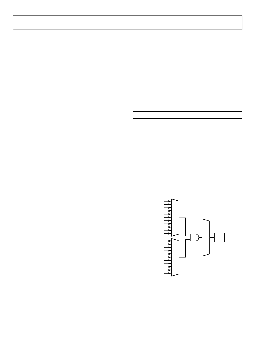
- IRQSTA, (read-only register) provides the current enabled
IRQ source status( effectively a logic AND of the IRQSIG
and IRQEN bits). When set to 1 that source will generate an
active IRQ request to the ARM7TDMI core. There is no
priority encoder or interrupt vector generation. This function
is implemented in software in a common interrupt handler
routine. All 32 bits are logically OR’ed to create a single IRQ
signal to the ARM7TDMI core.
FIQ
The FIQ (Fast Interrupt reQuest) is the exception signal to
enter the FIQ mode of the processor. It is provided to service
data transferor communication channel tasks with low latency.
The FIQ interface is identical to the IRQ interface providing the
second level interrupt (highest priority). Four 32-bit registers
are dedicated to FIQ, FIQSIG, FIQEN, FIQCLR and FIQSTA.
Bit 31 to 1 of FIQSTA are logically OR’ed to create the FIQ
signal to the core and the bit 0 of both the FIQ and IRQ
registers (FIQ source).
The logic for FIQEN and FIQCLR will not allow an interrupt
source to be enabled in both IRQ and FIQ masks. A bit set to ‘1’
in FIQEN will, as a side-effect, clear the same bit in IRQEN. A
bit set to ‘1’ in IRQEN will, as a side-effect, clear the same bit in
FIQEN. An interrupt source can be disabled in both IRQEN
and FIQEN masks.
Programmed interrupts
As the programmed interrupts are non-maskable, they are
controlled by another register, SWICFG, which write into both
IRQSTA and IRQSIG registers or/and FIQSTA and FIQSIG
registers at the same time.
The 32-bit register dedicated to software interrupt is SWICFG
described in Table 42a. This MMR allows the control of
programmed source interrupt.
Table 42 : SWICFG MMR Bit Descriptions
Bit
Description
31-3
Reserved
2
Programmed Interrupt-FIQ
Setting/clearing this bit correspond in setting/clearing
bit 1 of FIQSTA and FIQSIG
1
Programmed Interrupt-IRQ
Setting/clearing this bit correspond in setting/clearing
bit 1 of IRQSTA and IRQSIG
0
Reserved
Note that any interrupt signal must be active for at least the
minimum interrupt latency time, to be detected by the interrupt
controller and to be detected by user in the IRQSTA/FIQSTA
register.
05
99
4-
02
9
IR
QS
TA
FIQS
T
A
IR
QS
IG
FI
Q
S
IG
TIMER0
TIMER1
TIMER2
TIMER3
LIN H/W
FLASH/EE
PLL LOCK
ADC
UART
SPI
XIRQ
IR
QE
N
FI
Q
E
N
TIMER0
TIMER1
TIMER2
TIMER3
LIN H/W
FLASH/EE
PLL LOCK
ADC
UART
SPI
XIRQ
IRQ
FIQ
Figure 29: Interrupt Structure
相关PDF资料 |
PDF描述 |
|---|---|
| ADUC7034BCPZ | IC MCU FLASH 32K ANLG IO 48LFCSP |
| ADUC7036CCPZ | IC MCU 96K FLASH DUAL 48LFCSP |
| ADUC7039BCP6Z-RL | IC MCU ARM7 BATT SENSER 32LFCSP |
| ADUC7061BCPZ32 | IC MCU 16/32BIT 32KB 32LFCSP |
| ADUC7121BBCZ-RL | PRECISION ANALOG MCU I.C |
相关代理商/技术参数 |
参数描述 |
|---|---|
| ADUC7033 | 制造商:AD 制造商全称:Analog Devices 功能描述:Integrated Precision Battery Sensor For Automotive |
| ADUC7033BCPZ-8L | 制造商:Analog Devices 功能描述:Integrated Precision Battery Sensor 48-Pin LFCSP EP 制造商:Analog Devices 功能描述:INTEGRATED PRECISION BATTERY SENSOR 48LFCSP EP - Trays |
| ADUC7033BCPZ-8L-RL | 制造商:Analog Devices 功能描述:INTEGRATED PRECISION BATTERY SENSOR 48LFCSP EP - Tape and Reel |
| ADUC7033BSTZ-88 | 功能描述:IC BATT SENSOR PREC 48LQFP RoHS:是 类别:集成电路 (IC) >> PMIC - 电池管理 系列:- 标准包装:2,000 系列:Impedance Track™ 功能:燃料,电量检测计/监控器 电池化学:锂离子(Li-Ion) 电源电压:2.4 V ~ 2.6 V 工作温度:-40°C ~ 85°C 安装类型:表面贴装 封装/外壳:20-TSSOP(0.173",4.40mm 宽) 供应商设备封装:20-TSSOP 包装:带卷 (TR) 产品目录页面:1020 (CN2011-ZH PDF) 配用:BQ27350EVM-ND - BQ27350EVM 其它名称:296-21665-2 |
| ADUC7033BSTZ-88-RL | 功能描述:IC BATT SENSOR PREC 48LQFP RoHS:是 类别:集成电路 (IC) >> PMIC - 电池管理 系列:- 产品培训模块:Lead (SnPb) Finish for COTS Obsolescence Mitigation Program 标准包装:2,500 系列:- 功能:电池监控器 电池化学:碱性,锂离子,镍镉,镍金属氢化物 电源电压:1 V ~ 5.5 V 工作温度:-40°C ~ 85°C 安装类型:表面贴装 封装/外壳:SOT-23-6 供应商设备封装:SOT-6 包装:带卷 (TR) |
发布紧急采购,3分钟左右您将得到回复。