- 您现在的位置:买卖IC网 > PDF目录97874 > EC103D175 Thyristor Product Catalog PDF资料下载
参数资料
| 型号: | EC103D175 |
| 英文描述: | Thyristor Product Catalog |
| 中文描述: | 晶闸管产品目录 |
| 文件页数: | 64/224页 |
| 文件大小: | 2697K |
| 代理商: | EC103D175 |
第1页第2页第3页第4页第5页第6页第7页第8页第9页第10页第11页第12页第13页第14页第15页第16页第17页第18页第19页第20页第21页第22页第23页第24页第25页第26页第27页第28页第29页第30页第31页第32页第33页第34页第35页第36页第37页第38页第39页第40页第41页第42页第43页第44页第45页第46页第47页第48页第49页第50页第51页第52页第53页第54页第55页第56页第57页第58页第59页第60页第61页第62页第63页当前第64页第65页第66页第67页第68页第69页第70页第71页第72页第73页第74页第75页第76页第77页第78页第79页第80页第81页第82页第83页第84页第85页第86页第87页第88页第89页第90页第91页第92页第93页第94页第95页第96页第97页第98页第99页第100页第101页第102页第103页第104页第105页第106页第107页第108页第109页第110页第111页第112页第113页第114页第115页第116页第117页第118页第119页第120页第121页第122页第123页第124页第125页第126页第127页第128页第129页第130页第131页第132页第133页第134页第135页第136页第137页第138页第139页第140页第141页第142页第143页第144页第145页第146页第147页第148页第149页第150页第151页第152页第153页第154页第155页第156页第157页第158页第159页第160页第161页第162页第163页第164页第165页第166页第167页第168页第169页第170页第171页第172页第173页第174页第175页第176页第177页第178页第179页第180页第181页第182页第183页第184页第185页第186页第187页第188页第189页第190页第191页第192页第193页第194页第195页第196页第197页第198页第199页第200页第201页第202页第203页第204页第205页第206页第207页第208页第209页第210页第211页第212页第213页第214页第215页第216页第217页第218页第219页第220页第221页第222页第223页第224页
AN1006
Application Notes
http://www.teccor.com
AN1006 - 4
2002 Teccor Electronics
+1 972-580-7777
Thyristor Product Catalog
Power Rectifiers
The rectifier is a unidirectional device which conducts when for-
ward voltage (above 0.7 V) is applied.
To connect the rectifier:
1. Connect Anode to Collector Terminal (C).
2. Connect Cathode to Emitter Terminal (E).
To begin testing, perform the following procedures.
Procedure 1: VRRM and IRM
To measure the VRRM and IRM parameter:
1. Set Variable Collector Supply Voltage Range to 1500 V.
(2000 V on 370)
2. Set Horizontal knob to sufficient scale to allow viewing of
trace at the required voltage level (100 V/DIV for 400 V and
600 V devices and 50 V/DIV for 200 V devices).
3. Set Mode to Leakage.
4. Set Vertical knob to 100 A/DIV. (Due to leakage setting, the
CRT readout will be 100 nA per division.)
5. Set Terminal Selector to Emitter Grounded-Open Base.
6. Set Polarity to (–).
7. Set Power Dissipation to 2.2 W. (2W on 370)
8. Set Left-Right Terminal Jack Selector to correspond with
location of test fixture.
9. Increase Variable Collector Supply Voltage to the rated
VRRM of the device and observe the dot on the CRT. Read
across horizontally from the dot to the vertical current scale.
This measured value is the leakage current.
(Figure AN1006.2)
Figure AN1006.2
IRM = 340 nA at VRRM = 600 V
Procedure 2: VFM
Before testing, note the following:
A Kelvin test fixture is required for this test. If a Kelvin fixture is
not used, an error in measurement of VFM will result due to
voltage drop in fixture. If a Kelvin fixture is not available,
Figure AN1006.3 shows necessary information to wire a test
fixture with Kelvin connections.
Due to the current limitations of standard curve tracer
model 576, VFM cannot be tested at rated current without a Tek-
tronix model 176 high-current module. The procedure below is
done at IT(RMS) = 10 A (20 APK). This test parameter allows the
use of a standard curve tracer and still provides an estimate of
whether VFM is within specification.
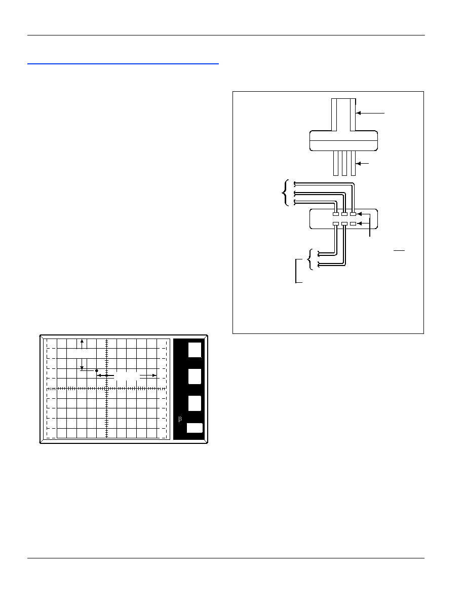
Figure AN1006.3
Instructions for Wiring Kelvin Socket
To measure the VFM parameter:
1. Set Variable Collector Supply Voltage Range to 15 Max
Peak Volts. (16 V on 370)
2. Set Horizontal knob to 0.5 V/DIV.
3. Set Mode to Norm.
4. Set Vertical knob to 2 A/DIV.
5. Set Power Dissipation to 220 W (100 W on 577).
6. Set Polarity to (+).
7. Set Left-Right Terminal Jack Selector to correspond with
location of test fixture.
8. Increase Variable Collector Supply Voltage until current
reaches 20 A.
WARNING: Limit test time to 15 seconds maximum.
To measure VFM, follow along horizontal scale to the point where
the trace crosses the 20 A axis. The distance from the left-hand
side of scale to the crossing point is the VFM value.
(Figure AN1006.4)
Note: Model 370 current is limited to 10 A.
VRRM
IRM
100
nA
100
V
PER
V
E
R
T
DIV
PER
H
O
R
I
Z
DIV
PER
S
T
E
P
()k
DIV
9m
PER
DIV
SOCKET
SOCKET PINS
One set of
pins wired to
Collector (C),
Base (B), and
Emitter (E)
Terminals
The pins which correspond to
the anode and cathode of the
device are wired to the terminals
marked CSENSE (MT2/Anode) and
ESENSE (MT1/Cathode). The gate
does not require a Kelvin
connection.
Socket used
must have two
sets of pins
相关PDF资料 |
PDF描述 |
|---|---|
| EC103D1 | Sensitive SCRs |
| EC103D | Sensitive SCRs |
| EC103D2 | Sensitive SCRs |
| EC103D3 | Sensitive SCRs |
| EC103M1 | PC 8C 8#20 PIN RECP |
相关代理商/技术参数 |
参数描述 |
|---|---|
| EC103D1AP | 功能描述:SEN SCR 400V .8A 12A TO92 RoHS:否 类别:分离式半导体产品 >> SCR - 单个 系列:- 其它有关文件:X00619 View All Specifications 产品目录绘图:SCR TO-92 Package 标准包装:1 系列:- SCR 型:灵敏栅极 电压 - 断路:600V 电压 - 栅极触发器 (Vgt)(最大):800mV 电压 - 导通状态 (Vtm)(最大):1.35V 电流 - 导通状态 (It (AV))(最大):500mA 电流 - 导通状态 (It (RMS))(最大):800mA 电流 - 栅极触发电流 (Igt)(最大):200µA 电流 - 维持(Ih):5mA 电流 - 断开状态(最大):1µA 电流 - 非重复电涌,50、60Hz (Itsm):9A,10A 工作温度:-40°C ~ 125°C 安装类型:通孔 封装/外壳:TO-226-3、TO-92-3(TO-226AA)成形引线 供应商设备封装:TO-92-3 包装:剪切带 (CT) 产品目录页面:1554 (CN2011-ZH PDF) 其它名称:497-9067-1 |
| EC103D1RP | 功能描述:SCR 400V .8A 12uA RoHS:否 制造商:STMicroelectronics 最大转折电流 IBO:480 A 额定重复关闭状态电压 VDRM:600 V 关闭状态漏泄电流(在 VDRM IDRM 下):5 uA 开启状态 RMS 电流 (It RMS): 正向电压下降:1.6 V 栅触发电压 (Vgt):1.3 V 最大栅极峰值反向电压:5 V 栅触发电流 (Igt):35 mA 保持电流(Ih 最大值):75 mA 安装风格:Through Hole 封装 / 箱体:TO-220 封装:Tube |
| EC103D1WX | 制造商:NXP Semiconductors 功能描述:1000 制造商:NXP Semiconductors 功能描述:EC103D1W/SC-73/REEL7// - Tape and Reel 制造商:NXP Semiconductors 功能描述:SCR SENS GATE 400V SC-73 制造商:NXP Semiconductors 功能描述:SCRs 400v Sc-73 Scr Sens Gate |
| EC103D2 | 功能描述:SCR 400V .8A 50uA Sensing RoHS:否 制造商:STMicroelectronics 最大转折电流 IBO:480 A 额定重复关闭状态电压 VDRM:600 V 关闭状态漏泄电流(在 VDRM IDRM 下):5 uA 开启状态 RMS 电流 (It RMS): 正向电压下降:1.6 V 栅触发电压 (Vgt):1.3 V 最大栅极峰值反向电压:5 V 栅触发电流 (Igt):35 mA 保持电流(Ih 最大值):75 mA 安装风格:Through Hole 封装 / 箱体:TO-220 封装:Tube |
| EC103D275 | 功能描述:SCR 400V .8A 50uA RoHS:否 制造商:STMicroelectronics 最大转折电流 IBO:480 A 额定重复关闭状态电压 VDRM:600 V 关闭状态漏泄电流(在 VDRM IDRM 下):5 uA 开启状态 RMS 电流 (It RMS): 正向电压下降:1.6 V 栅触发电压 (Vgt):1.3 V 最大栅极峰值反向电压:5 V 栅触发电流 (Igt):35 mA 保持电流(Ih 最大值):75 mA 安装风格:Through Hole 封装 / 箱体:TO-220 封装:Tube |
发布紧急采购,3分钟左右您将得到回复。