- 您现在的位置:买卖IC网 > PDF目录97874 > EC103D175 Thyristor Product Catalog PDF资料下载
参数资料
| 型号: | EC103D175 |
| 英文描述: | Thyristor Product Catalog |
| 中文描述: | 晶闸管产品目录 |
| 文件页数: | 98/224页 |
| 文件大小: | 2697K |
| 代理商: | EC103D175 |
第1页第2页第3页第4页第5页第6页第7页第8页第9页第10页第11页第12页第13页第14页第15页第16页第17页第18页第19页第20页第21页第22页第23页第24页第25页第26页第27页第28页第29页第30页第31页第32页第33页第34页第35页第36页第37页第38页第39页第40页第41页第42页第43页第44页第45页第46页第47页第48页第49页第50页第51页第52页第53页第54页第55页第56页第57页第58页第59页第60页第61页第62页第63页第64页第65页第66页第67页第68页第69页第70页第71页第72页第73页第74页第75页第76页第77页第78页第79页第80页第81页第82页第83页第84页第85页第86页第87页第88页第89页第90页第91页第92页第93页第94页第95页第96页第97页当前第98页第99页第100页第101页第102页第103页第104页第105页第106页第107页第108页第109页第110页第111页第112页第113页第114页第115页第116页第117页第118页第119页第120页第121页第122页第123页第124页第125页第126页第127页第128页第129页第130页第131页第132页第133页第134页第135页第136页第137页第138页第139页第140页第141页第142页第143页第144页第145页第146页第147页第148页第149页第150页第151页第152页第153页第154页第155页第156页第157页第158页第159页第160页第161页第162页第163页第164页第165页第166页第167页第168页第169页第170页第171页第172页第173页第174页第175页第176页第177页第178页第179页第180页第181页第182页第183页第184页第185页第186页第187页第188页第189页第190页第191页第192页第193页第194页第195页第196页第197页第198页第199页第200页第201页第202页第203页第204页第205页第206页第207页第208页第209页第210页第211页第212页第213页第214页第215页第216页第217页第218页第219页第220页第221页第222页第223页第224页
Application Notes
AN1009
2002 Teccor Electronics
AN1009 - 3
http://www.teccor.com
Thyristor Product Catalog
+1 972-580-7777
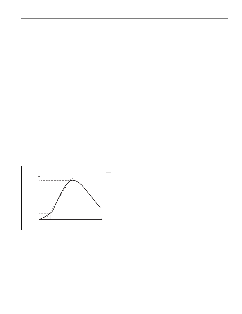
Double-exponential Impulse Waveform
A double-exponential impulse waveform or waveshape of current
or voltage is designated by a combination of two numbers (tr/td or
tr x td s). The first number is an exponential rise time (tr) or wave
front and the second number is an exponential decay time (td) or
wave tail. The rise time (tr) is the maximum rise time permitted.
The decay time (td) is the minimum time permitted. Both the tr and
the td are in the same units of time, typically microseconds, des-
ignated at the end of the waveform description as defined by
ANSI/IEEE C62.1-1989.
The rise time (tr) of a current waveform is 1.25 times the time for
the current to increase from 10% to 90% of peak value. See Fig-
ure AN1009.5.
tr = Rise Time = 1.25 [tc – ta]
tr = 1.25 [t(0.9 IPK) – t(0.1 IPK)] = T1 – T0
The rise time (tr) of a voltage waveform is 1.67 times the time for
the voltage to increase from 30% to 90% of peak value. (Figure
AN1009.5)
tr = Rise Time = 1.67 [tc – tb]
tr = 1.67 [t(0.9 VPK) – t(0.3 VPK)] = T1 – T0
The decay time (td) of a waveform is the time from virtual zero
(10% of peak for current or 30% of peak for voltage) to the time
at which one-half (50%) of the peak value is reached on the wave
tail. (Figure AN1009.5)
Current Waveform td = Decay Time
= [t(0.5 IPK) – t(0.1 IPK)] = T2 – T0
Voltage Waveform td = Decay Time
= [t(0.5 VPK) – t(0.3 VPK)] = T2 – T0
Figure AN1009.5
Double-exponential Impulse Waveform
Failure Modes of Thyristor
Thyristor failures may be broadly classified as either degrading
or catastrophic. A degrading type of failure is defined as a
change in some characteristic which may or may not cause a cat-
astrophic failure, but could show up as a latent failure. Cata-
strophic failure is when a device exhibits a sudden change in
characteristic that renders it inoperable. To minimize degrading
and catastrophic failures, devices must be operated within maxi-
mum ratings at all times.
Degradation Failures
A significant change of on-state, gate, or switching characteris-
tics is quite rare. The most vulnerable characteristic is blocking
voltage. This type of degradation increases with rising operating
voltage and temperature levels.
Catastrophic Failures
A catastrophic failure can occur whenever the thyristor is oper-
ated beyond its published ratings. The most common failure
mode is an electrical short between the main terminals, although
a triac can fail in a half-wave condition. It is possible, but not
probable, that the resulting short-circuit current could melt the
internal parts of the device which could result in an open circuit.
Failure Causes
Most thyristor failures occur due to exceeding the maximum
operating ratings of the device. Overvoltage or overcurrent oper-
ations are the most probable cause for failure. Overvoltage fail-
ures may be due to excessive voltage transients or may also
occur if inadequate cooling allows the operating temperature to
rise above the maximum allowable junction temperature. Over-
current failures are generally caused by improper fusing or circuit
protection, surge current from load initiation, load abuse, or load
failure. Another common cause of device failure is incorrect han-
dling procedures used in the manufacturing process. Mechanical
damage in the form of excessive mounting torque and/or force
applied to the terminals or leads can transmit stresses to the
internal thyristor chip and cause cracks in the chip which may not
show up until the device is thermally cycled.
Prevention of Failures
Careful selection of the correct device for the application’s oper-
ating parameters and environment will go a long way toward
extending the operating life of the thyristor. Good design practice
should also limit the maximum current through the main terminals
to 75% of the device rating. Correct mounting and forming of the
leads also help ensure against infant mortality and latent failures.
The two best ways to ensure long life of a thyristor is by proper
heat sink methods and correct voltage rating selection for worst
case conditions. Overheating, overvoltage, and surge currents
are the main killers of semiconductors.
Most Common Thyristor Failure Mode
When a thyristor is electrically or physically abused and fails either
by degradation or a catastrophic means, it will short (full-wave or
half-wave) as its normal failure mode. Rarely does it fail open
circuit. The circuit designer should add line breaks, fuses, over-
temperature interrupters or whatever is necessary to protect the
end user and property if a shorted or partially shorted thyristor
offers a safety hazard.
Virtual Start of Wavefront
(Peak Value)
100%
90%
50%
0%
10%
30%
ta tb
T0
tc T1
T2
Time
Percent
of
Current
or
Voltage
Decay = e -
t
1.44 T2
相关PDF资料 |
PDF描述 |
|---|---|
| EC103D1 | Sensitive SCRs |
| EC103D | Sensitive SCRs |
| EC103D2 | Sensitive SCRs |
| EC103D3 | Sensitive SCRs |
| EC103M1 | PC 8C 8#20 PIN RECP |
相关代理商/技术参数 |
参数描述 |
|---|---|
| EC103D1AP | 功能描述:SEN SCR 400V .8A 12A TO92 RoHS:否 类别:分离式半导体产品 >> SCR - 单个 系列:- 其它有关文件:X00619 View All Specifications 产品目录绘图:SCR TO-92 Package 标准包装:1 系列:- SCR 型:灵敏栅极 电压 - 断路:600V 电压 - 栅极触发器 (Vgt)(最大):800mV 电压 - 导通状态 (Vtm)(最大):1.35V 电流 - 导通状态 (It (AV))(最大):500mA 电流 - 导通状态 (It (RMS))(最大):800mA 电流 - 栅极触发电流 (Igt)(最大):200µA 电流 - 维持(Ih):5mA 电流 - 断开状态(最大):1µA 电流 - 非重复电涌,50、60Hz (Itsm):9A,10A 工作温度:-40°C ~ 125°C 安装类型:通孔 封装/外壳:TO-226-3、TO-92-3(TO-226AA)成形引线 供应商设备封装:TO-92-3 包装:剪切带 (CT) 产品目录页面:1554 (CN2011-ZH PDF) 其它名称:497-9067-1 |
| EC103D1RP | 功能描述:SCR 400V .8A 12uA RoHS:否 制造商:STMicroelectronics 最大转折电流 IBO:480 A 额定重复关闭状态电压 VDRM:600 V 关闭状态漏泄电流(在 VDRM IDRM 下):5 uA 开启状态 RMS 电流 (It RMS): 正向电压下降:1.6 V 栅触发电压 (Vgt):1.3 V 最大栅极峰值反向电压:5 V 栅触发电流 (Igt):35 mA 保持电流(Ih 最大值):75 mA 安装风格:Through Hole 封装 / 箱体:TO-220 封装:Tube |
| EC103D1WX | 制造商:NXP Semiconductors 功能描述:1000 制造商:NXP Semiconductors 功能描述:EC103D1W/SC-73/REEL7// - Tape and Reel 制造商:NXP Semiconductors 功能描述:SCR SENS GATE 400V SC-73 制造商:NXP Semiconductors 功能描述:SCRs 400v Sc-73 Scr Sens Gate |
| EC103D2 | 功能描述:SCR 400V .8A 50uA Sensing RoHS:否 制造商:STMicroelectronics 最大转折电流 IBO:480 A 额定重复关闭状态电压 VDRM:600 V 关闭状态漏泄电流(在 VDRM IDRM 下):5 uA 开启状态 RMS 电流 (It RMS): 正向电压下降:1.6 V 栅触发电压 (Vgt):1.3 V 最大栅极峰值反向电压:5 V 栅触发电流 (Igt):35 mA 保持电流(Ih 最大值):75 mA 安装风格:Through Hole 封装 / 箱体:TO-220 封装:Tube |
| EC103D275 | 功能描述:SCR 400V .8A 50uA RoHS:否 制造商:STMicroelectronics 最大转折电流 IBO:480 A 额定重复关闭状态电压 VDRM:600 V 关闭状态漏泄电流(在 VDRM IDRM 下):5 uA 开启状态 RMS 电流 (It RMS): 正向电压下降:1.6 V 栅触发电压 (Vgt):1.3 V 最大栅极峰值反向电压:5 V 栅触发电流 (Igt):35 mA 保持电流(Ih 最大值):75 mA 安装风格:Through Hole 封装 / 箱体:TO-220 封装:Tube |
发布紧急采购,3分钟左右您将得到回复。