- 您现在的位置:买卖IC网 > PDF目录97874 > EC103D175 Thyristor Product Catalog PDF资料下载
参数资料
| 型号: | EC103D175 |
| 英文描述: | Thyristor Product Catalog |
| 中文描述: | 晶闸管产品目录 |
| 文件页数: | 70/224页 |
| 文件大小: | 2697K |
| 代理商: | EC103D175 |
第1页第2页第3页第4页第5页第6页第7页第8页第9页第10页第11页第12页第13页第14页第15页第16页第17页第18页第19页第20页第21页第22页第23页第24页第25页第26页第27页第28页第29页第30页第31页第32页第33页第34页第35页第36页第37页第38页第39页第40页第41页第42页第43页第44页第45页第46页第47页第48页第49页第50页第51页第52页第53页第54页第55页第56页第57页第58页第59页第60页第61页第62页第63页第64页第65页第66页第67页第68页第69页当前第70页第71页第72页第73页第74页第75页第76页第77页第78页第79页第80页第81页第82页第83页第84页第85页第86页第87页第88页第89页第90页第91页第92页第93页第94页第95页第96页第97页第98页第99页第100页第101页第102页第103页第104页第105页第106页第107页第108页第109页第110页第111页第112页第113页第114页第115页第116页第117页第118页第119页第120页第121页第122页第123页第124页第125页第126页第127页第128页第129页第130页第131页第132页第133页第134页第135页第136页第137页第138页第139页第140页第141页第142页第143页第144页第145页第146页第147页第148页第149页第150页第151页第152页第153页第154页第155页第156页第157页第158页第159页第160页第161页第162页第163页第164页第165页第166页第167页第168页第169页第170页第171页第172页第173页第174页第175页第176页第177页第178页第179页第180页第181页第182页第183页第184页第185页第186页第187页第188页第189页第190页第191页第192页第193页第194页第195页第196页第197页第198页第199页第200页第201页第202页第203页第204页第205页第206页第207页第208页第209页第210页第211页第212页第213页第214页第215页第216页第217页第218页第219页第220页第221页第222页第223页第224页
Application Notes
AN1006
2002 Teccor Electronics
AN1006 - 9
http://www.teccor.com
Thyristor Product Catalog
+1 972-580-7777
3. Set Max Peak Volts to 75 V. (80 V on 370)
4. Set Mode to DC.
5. Set Horizontal knob to Step Generator.
6. Set Vertical knob to approximately 10% of the maximum IH
specified.
Note: Due to large variation of holding current values, the
scale may have to be adjusted to observe holding current.
7. Set Number of Steps to 1.
8. Set Step/Offset Polarity to non-inverted (button extended,
on 577 button depressed).
9. Set Offset by depressing 0 (zero). (Press Aid and Oppose at
same time on 370.)
10. Set Terminal Selector to Step Generator-Emitter Grounded.
Procedure 8: IH(Forward)
To measure the IH (Forward) parameter:
1. Set Polarity to (+).
2. Set Left-Right Terminal Jack Selector to correspond with
location of test fixture.
3. Increase Variable Collector Supply Voltage to maximum
position (100).
4. Set Step Family by depressing Single.
This could possibly cause the dot on the CRT to disappear,
depending on the vertical scale selected).
5. Decrease Variable Collector Supply Voltage to the point
where the line on the CRT changes to a dot. The position of
the beginning point of the line, just before the line becomes a
dot, represents the holding current value.
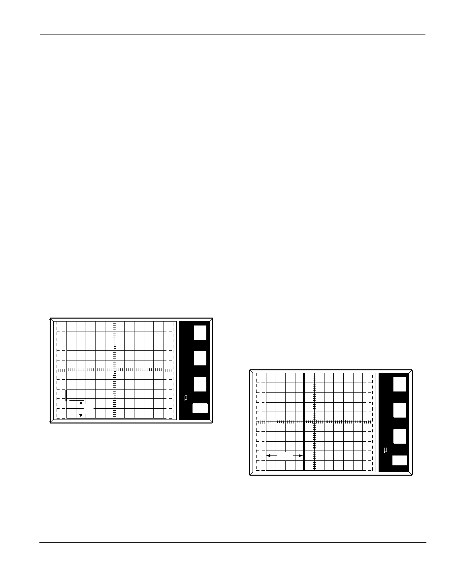
(Figure AN1006.13)
Figure AN1006.13 IH (Forward) = 8.2 mA
Procedure 9: IH(Reverse)
To measure the IH (Reverse) parameter:
1. Set Polarity to (–).
2. Repeat Procedure 7 measuring IH(Reverse). (Read measure-
ments from upper right corner of the screen.)
Procedure 10: IGT
To measure the IGT parameter:
1. Set Polarity to (+).
2. Set Number of Steps to 1. (Set number of steps to 0 (zero)
on 370.)
3. Set Offset by depressing Aid. (On 577, also set Zero button
to Offset. Button is extended.)
4. Set Offset Multiplier to 0 (zero). (Press Aid and Oppose at
same time on 370.)
5. Set Terminal Selector to Step Generator-Emitter Grounded.
6. Set Mode to Norm.
7. Set Max Peak Volts to 15 V. (16 V on 370)
8. Set Power Dissipation to 10 W.
9. Set Step Family by depressing Single.
10. Set Horizontal knob to 2 V/DIV.
11. Set Vertical knob to 50 mA/DIV.
12. Set Step/Offset Polarity to non-inverted position (button
extended, on 577 button depressed).
13. Set Variable Collector Supply Voltage until voltage
reaches 12 V on CRT.
14. After 12 V setting is completed, change Horizontal knob to
Step Generator.
Procedure 11: IGT – Quadrant I [MT2 (+) Gate (+)]
To measure the IGT – Quadrant I parameter:
1. Set Step/Offset Amplitude to approximately 10% of rated
IGT.
2. Set Left-Right Terminal Jack Selector to correspond with
location of test fixture.
3. Gradually increase Offset Multiplier until device reaches
conduction point. (Figure AN1006.14) Measure IGT by follow-
ing horizontal axis to the point where the vertical line passes
through the axis. This measured value is IGT. (On 370, IGT is
numerically displayed on screen under offset value.)
Figure AN1006.14 IGT in Quadrant I = 18.8 mA
5
mA
100m
PER
V
E
R
T
DIV
PER
H
O
R
I
Z
DIV
PER
S
T
E
P
()k
DIV
9m
PER
DIV
50
mA
IH
50
mA
10
PER
V
E
R
T
DIV
PER
H
O
R
I
Z
DIV
PER
S
T
E
P
()k
DIV
9m
PER
DIV
5
mA
IGT
相关PDF资料 |
PDF描述 |
|---|---|
| EC103D1 | Sensitive SCRs |
| EC103D | Sensitive SCRs |
| EC103D2 | Sensitive SCRs |
| EC103D3 | Sensitive SCRs |
| EC103M1 | PC 8C 8#20 PIN RECP |
相关代理商/技术参数 |
参数描述 |
|---|---|
| EC103D1AP | 功能描述:SEN SCR 400V .8A 12A TO92 RoHS:否 类别:分离式半导体产品 >> SCR - 单个 系列:- 其它有关文件:X00619 View All Specifications 产品目录绘图:SCR TO-92 Package 标准包装:1 系列:- SCR 型:灵敏栅极 电压 - 断路:600V 电压 - 栅极触发器 (Vgt)(最大):800mV 电压 - 导通状态 (Vtm)(最大):1.35V 电流 - 导通状态 (It (AV))(最大):500mA 电流 - 导通状态 (It (RMS))(最大):800mA 电流 - 栅极触发电流 (Igt)(最大):200µA 电流 - 维持(Ih):5mA 电流 - 断开状态(最大):1µA 电流 - 非重复电涌,50、60Hz (Itsm):9A,10A 工作温度:-40°C ~ 125°C 安装类型:通孔 封装/外壳:TO-226-3、TO-92-3(TO-226AA)成形引线 供应商设备封装:TO-92-3 包装:剪切带 (CT) 产品目录页面:1554 (CN2011-ZH PDF) 其它名称:497-9067-1 |
| EC103D1RP | 功能描述:SCR 400V .8A 12uA RoHS:否 制造商:STMicroelectronics 最大转折电流 IBO:480 A 额定重复关闭状态电压 VDRM:600 V 关闭状态漏泄电流(在 VDRM IDRM 下):5 uA 开启状态 RMS 电流 (It RMS): 正向电压下降:1.6 V 栅触发电压 (Vgt):1.3 V 最大栅极峰值反向电压:5 V 栅触发电流 (Igt):35 mA 保持电流(Ih 最大值):75 mA 安装风格:Through Hole 封装 / 箱体:TO-220 封装:Tube |
| EC103D1WX | 制造商:NXP Semiconductors 功能描述:1000 制造商:NXP Semiconductors 功能描述:EC103D1W/SC-73/REEL7// - Tape and Reel 制造商:NXP Semiconductors 功能描述:SCR SENS GATE 400V SC-73 制造商:NXP Semiconductors 功能描述:SCRs 400v Sc-73 Scr Sens Gate |
| EC103D2 | 功能描述:SCR 400V .8A 50uA Sensing RoHS:否 制造商:STMicroelectronics 最大转折电流 IBO:480 A 额定重复关闭状态电压 VDRM:600 V 关闭状态漏泄电流(在 VDRM IDRM 下):5 uA 开启状态 RMS 电流 (It RMS): 正向电压下降:1.6 V 栅触发电压 (Vgt):1.3 V 最大栅极峰值反向电压:5 V 栅触发电流 (Igt):35 mA 保持电流(Ih 最大值):75 mA 安装风格:Through Hole 封装 / 箱体:TO-220 封装:Tube |
| EC103D275 | 功能描述:SCR 400V .8A 50uA RoHS:否 制造商:STMicroelectronics 最大转折电流 IBO:480 A 额定重复关闭状态电压 VDRM:600 V 关闭状态漏泄电流(在 VDRM IDRM 下):5 uA 开启状态 RMS 电流 (It RMS): 正向电压下降:1.6 V 栅触发电压 (Vgt):1.3 V 最大栅极峰值反向电压:5 V 栅触发电流 (Igt):35 mA 保持电流(Ih 最大值):75 mA 安装风格:Through Hole 封装 / 箱体:TO-220 封装:Tube |
发布紧急采购,3分钟左右您将得到回复。