- 您现在的位置:买卖IC网 > PDF目录296800 > PEF22508E (INFINEON TECHNOLOGIES AG) DATACOM, PCM TRANSCEIVER, PBGA256 PDF资料下载
参数资料
| 型号: | PEF22508E |
| 厂商: | INFINEON TECHNOLOGIES AG |
| 元件分类: | 数字传输电路 |
| 英文描述: | DATACOM, PCM TRANSCEIVER, PBGA256 |
| 封装: | 17 X 17 MM, 1 MM PITCH, PLASTIC, LBGA-256 |
| 文件页数: | 111/193页 |
| 文件大小: | 10683K |
| 代理商: | PEF22508E |
第1页第2页第3页第4页第5页第6页第7页第8页第9页第10页第11页第12页第13页第14页第15页第16页第17页第18页第19页第20页第21页第22页第23页第24页第25页第26页第27页第28页第29页第30页第31页第32页第33页第34页第35页第36页第37页第38页第39页第40页第41页第42页第43页第44页第45页第46页第47页第48页第49页第50页第51页第52页第53页第54页第55页第56页第57页第58页第59页第60页第61页第62页第63页第64页第65页第66页第67页第68页第69页第70页第71页第72页第73页第74页第75页第76页第77页第78页第79页第80页第81页第82页第83页第84页第85页第86页第87页第88页第89页第90页第91页第92页第93页第94页第95页第96页第97页第98页第99页第100页第101页第102页第103页第104页第105页第106页第107页第108页第109页第110页当前第111页第112页第113页第114页第115页第116页第117页第118页第119页第120页第121页第122页第123页第124页第125页第126页第127页第128页第129页第130页第131页第132页第133页第134页第135页第136页第137页第138页第139页第140页第141页第142页第143页第144页第145页第146页第147页第148页第149页第150页第151页第152页第153页第154页第155页第156页第157页第158页第159页第160页第161页第162页第163页第164页第165页第166页第167页第168页第169页第170页第171页第172页第173页第174页第175页第176页第177页第178页第179页第180页第181页第182页第183页第184页第185页第186页第187页第188页第189页第190页第191页第192页第193页
OctalLIU
TM
PEF 22508 E
Pin Descriptions
Data Sheet
24
Rev. 1.0, 2005-06-02
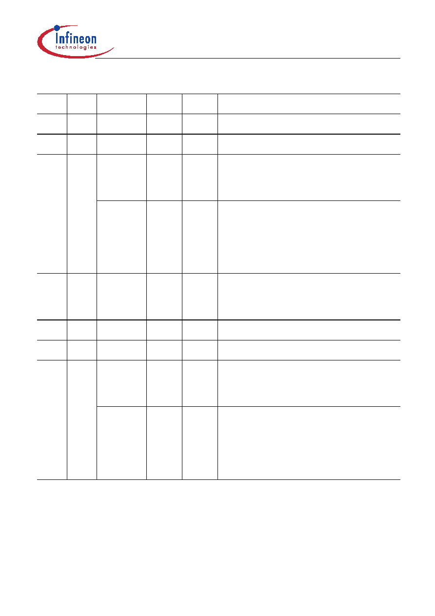
C7
XL3.1
I (analog) –
Transmit Line 3, port 1
Analog transmit input 1.
C6
XL4.1
I (analog) –
Transmit Line 4, port 1
Analog transmit input 2.
D4
XL1.2
O
(analog)
–
Transmit Line 1, port 2
Analog output to the external transformer. Selected if
LIM1.DRS is cleared. After reset this pin is in high-
impedance state until bit MR0.XC1 is set and
XPM2.XLT is cleared.
XOID2
O
–
Transmit Optical Interface Data, port 2
Data in CMI code is shifted out with 50% or 100% duty
cycle on both transitions of XCLK2 according to the CMI
coding. Output polarity is selected by bit LIM0.XDOS
(after reset: data is sent active high). The single-rail
mode is selected if LIM1.DRS is set and MR0.XC1 is
cleared. After reset this pin is in high-impedance state
until register LIM1.DRS is set and XPM2.XLT is cleared.
D3
XL2.2
O
(analog)
–
Transmit Line 2, port 2
Analog output for the external transformer. Selected if
LIM1.DRS is cleared. After reset this pin is in high-
impedance state until bit MR0.XC1 is set and
XPM2.XLT is cleared.
C4
XL3.2
I (analog) –
Transmit Line 3, port 2
Analog transmit input 1.
C3
XL4.2
I (analog) –
Transmit Line 4, port 2
Analog transmit input 2.
N4
XL1.3
O
(analog)
–
Transmit Line 1, port 3
Analog output to the external transformer. Selected if
LIM1.DRS is cleared. After reset this pin is in high-
impedance state until bit MR0.XC1 is set and
XPM2.XLT is cleared.
XOID3
O
–
Transmit Optical Interface Data, port 3
Data in CMI code is shifted out with 50% or 100% duty
cycle on both transitions of XCLK3 according to the CMI
coding. Output polarity is selected by bit LIM0.XDOS
(after reset: data is sent active high). The single-rail
mode is selected if LIM1.DRS is set and MR0.XC1 is
cleared. After reset this pin is in high-impedance state
until register LIM1.DRS is set and XPM2.XLT is cleared.
Table 1
I/O Signals (cont’d)
Pin No. Ball
No.
Name
Pin Type Buffer
Type
Function
相关PDF资料 |
PDF描述 |
|---|---|
| PEF22554E | DATACOM, FRAMER, PBGA160 |
| PEF22554HT | DATACOM, FRAMER, PQFP144 |
| PES12-42S-N0024 | |
| PESD3V3V4UK,132 | 25 W, UNIDIRECTIONAL, 4 ELEMENT, SILICON, TVS DIODE |
| PF38F3050L0YUQ3A | SPECIALTY MEMORY CIRCUIT, PBGA88 |
相关代理商/技术参数 |
参数描述 |
|---|---|
| PEF22508EV1.1-G | 功能描述:网络控制器与处理器 IC T/E RoHS:否 制造商:Micrel 产品:Controller Area Network (CAN) 收发器数量: 数据速率: 电源电流(最大值):595 mA 最大工作温度:+ 85 C 安装风格:SMD/SMT 封装 / 箱体:PBGA-400 封装:Tray |
| PEF22508EV11G | 制造商:Rochester Electronics LLC 功能描述: 制造商:Infineon Technologies AG 功能描述: |
| PEF22508EV11GXP | 制造商:Lantiq 功能描述:LINE INTERFACE UNITS |
| PEF22508EV11GXT | 制造商:Lantiq 功能描述:LINE INTERFACE UNITS |
| PEF22509EV1.1 | 制造商:Infineon Technologies AG 功能描述:SP000205605_T/E ASIC_TY_PB |
发布紧急采购,3分钟左右您将得到回复。