- 您现在的位置:买卖IC网 > PDF目录69400 > SYM53C040169BGA SCSI BUS CONTROLLER, PBGA169 PDF资料下载
参数资料
| 型号: | SYM53C040169BGA |
| 元件分类: | 总线控制器 |
| 英文描述: | SCSI BUS CONTROLLER, PBGA169 |
| 封装: | BGA-169 |
| 文件页数: | 42/198页 |
| 文件大小: | 2732K |
| 代理商: | SYM53C040169BGA |
第1页第2页第3页第4页第5页第6页第7页第8页第9页第10页第11页第12页第13页第14页第15页第16页第17页第18页第19页第20页第21页第22页第23页第24页第25页第26页第27页第28页第29页第30页第31页第32页第33页第34页第35页第36页第37页第38页第39页第40页第41页当前第42页第43页第44页第45页第46页第47页第48页第49页第50页第51页第52页第53页第54页第55页第56页第57页第58页第59页第60页第61页第62页第63页第64页第65页第66页第67页第68页第69页第70页第71页第72页第73页第74页第75页第76页第77页第78页第79页第80页第81页第82页第83页第84页第85页第86页第87页第88页第89页第90页第91页第92页第93页第94页第95页第96页第97页第98页第99页第100页第101页第102页第103页第104页第105页第106页第107页第108页第109页第110页第111页第112页第113页第114页第115页第116页第117页第118页第119页第120页第121页第122页第123页第124页第125页第126页第127页第128页第129页第130页第131页第132页第133页第134页第135页第136页第137页第138页第139页第140页第141页第142页第143页第144页第145页第146页第147页第148页第149页第150页第151页第152页第153页第154页第155页第156页第157页第158页第159页第160页第161页第162页第163页第164页第165页第166页第167页第168页第169页第170页第171页第172页第173页第174页第175页第176页第177页第178页第179页第180页第181页第182页第183页第184页第185页第186页第187页第188页第189页第190页第191页第192页第193页第194页第195页第196页第197页第198页
System Register FF30h . . . . . . . . . . . . . . . . . . . . . . . . . . . . . . . . . . . . . . . . . . . . . . . . . . . . . . System Register FF31h
8-16
SYM53C040 DATA MANUAL VERSION 2.0
PRELIMINARY
These read/write register bits determine if pulldowns are active on the I/O pins
MPIO3_0, MPIO3_1, MPIO3_2, and MPIO3_3. A value of 1 indicates the pulldown is
active, a value of 0 indicates the pulldown is inactive.
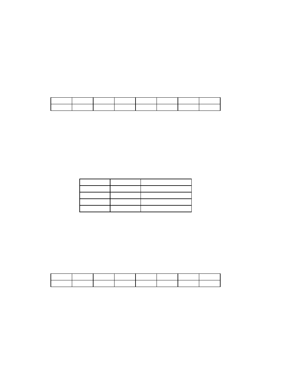
System Register FF30h
Multi-Purpose LED Bank 0L Output (MLO0L)
Read/write
MLO0L Bits 7-0 MLO0_3A, MLO0_3B, MLO0_2A, MLO0_2B, MLO0_1A, MLO0_1B,
MLO0_0A, MLO0_0Ba (Multi-purpose LED Bank 0L Output)
The bits in this registers control the Multi-Purpose LED Bank 0 pins MPLED0_3,
MPLED0_2, MPLED0_1, and MPLED0_0. Two bits are used to control each LED,
according to Table 8-5.
The slow blink and fast blink rates are defined in the LBR register FF02h. All LED pins
have 16 mA open-drain drivers. Turning the LED off (mlox_xa = 0 and mlox_xb = 0)
effectively tri-states the driver.
System Register FF31h
Multi-Purpose LED Bank 0H Output (MLO0H)
Read/write
Bits 7-0 MLO0_7A, MLO0_7B, MLO0_6A, MLO0_6B, MLO0_5A, MLO0_5B,
MLO0_4A, MLO0_4B (Multi-Purpose LED Bank 0H Output)
The bits in this register controls the Multi-Purpose LED Bank 0 pins MPLED0_7,
MPLED0_6, MPLED0_5, and MPLED0_4. Two bits are used to control each LED,
according to Table 8-5 page 8-16.
MLO0_3A
MLO0_3B
MLO0_2A
MLO0_2B
MLO0_1A
MLO0_1B
MLO0_0A
MLO0_0B
76543210
Defaults:
00000000
Table 8-5
LED behavior
MLOx_xA
MLOx_xB
LED behavior
00OFF
01slow blink
10fast blink
1
CONSTANT ON
MLO0_7A
MLO0_7B
MLO0_6A
MLO0_6B
MLO0_5A
MLO0_5B
MLO0_4A
MLO0_4B
76543210
Defaults:
00000000
相关PDF资料 |
PDF描述 |
|---|---|
| SYM53C180I2 | SCSI BUS CONTROLLER, PBGA192 |
| SYM53C895V5 | SCSI BUS CONTROLLER, PBGA272 |
| SZ20360 | SINGLE COLOR LED, NATURAL WHITE, 10.3 mm |
| SZW05A0A | T-1 SINGLE COLOR LED, PURE WHITE, 2.9 mm |
| SZWW5A0A | T-1 SINGLE COLOR LED, WARM WHITE, 2.9 mm |
相关代理商/技术参数 |
参数描述 |
|---|---|
| SYM53C1010 | 制造商:未知厂家 制造商全称:未知厂家 功能描述:Interface IC |
| SYM53C141 | 制造商:未知厂家 制造商全称:未知厂家 功能描述:Interface IC |
| SYM53C400A | 制造商:SYMBIOS 功能描述: |
| SYM53C770 | 制造商:未知厂家 制造商全称:未知厂家 功能描述:SCSI Bus Interface/Controller |
| SYM53C876E(PBGA) | 制造商:未知厂家 制造商全称:未知厂家 功能描述:SCSI Bus Interface/Controller |
发布紧急采购,3分钟左右您将得到回复。