- 您现在的位置:买卖IC网 > PDF目录4578 > IDT88P8344BHGI (IDT, Integrated Device Technology Inc)IC SPI3-SPI4 EXCHANGE 820-PBGA PDF资料下载
参数资料
| 型号: | IDT88P8344BHGI |
| 厂商: | IDT, Integrated Device Technology Inc |
| 文件页数: | 39/98页 |
| 文件大小: | 0K |
| 描述: | IC SPI3-SPI4 EXCHANGE 820-PBGA |
| 标准包装: | 24 |
| 系列: | * |
| 其它名称: | 88P8344BHGI |
第1页第2页第3页第4页第5页第6页第7页第8页第9页第10页第11页第12页第13页第14页第15页第16页第17页第18页第19页第20页第21页第22页第23页第24页第25页第26页第27页第28页第29页第30页第31页第32页第33页第34页第35页第36页第37页第38页当前第39页第40页第41页第42页第43页第44页第45页第46页第47页第48页第49页第50页第51页第52页第53页第54页第55页第56页第57页第58页第59页第60页第61页第62页第63页第64页第65页第66页第67页第68页第69页第70页第71页第72页第73页第74页第75页第76页第77页第78页第79页第80页第81页第82页第83页第84页第85页第86页第87页第88页第89页第90页第91页第92页第93页第94页第95页第96页第97页第98页
44
IDT88P8344 SPI EXCHANGE 4 x SPI-3 TO SPI-4
INDUSTRIALTEMPERATURERANGE
APRIL 10, 2006
example,aSPI-4clockof400MHzgivesadataunitintervalof1.25ns,somatch
the lengths within the entire signal group to within 625 ps, or 3 inches.
3) Keep P and N signals within a differential pair on the same layer with the
minimumtracespacingpossiblewhilestillbeingabletoget100ohmsdifferential
impedance (tightly edge-coupled pair routing).
4) Route all differential pairs as 100 Ohm embedded differential stripline (on
an inner layer, referencing ground planes). For example, 7 mil wide 1/2 oz
copper traces separated by 10 mils, with 10 mil dielectric spacing to ground
planes above and below the traces gives 100 Ohms of differential impedance
for FR-4 with a relative dielectric constant (
ε
R or DK) of 4.2. If the edge to edge
spacingbetweenadjacentdifferentialpairtracesis20mils,crosstalkis0.6%for
signalsterminatedtowithina10%impedancematch.Iftheedgetoedgespacing
betweenadifferentialpairandanLVTTLsignalis30milswithintheparameters
of this example, crosstalk is 0.8% (with the LVTTL signals series terminated).
Use a field solver for more accurate results.
5) Follow the SPI-3 layout guidelines for any routed SPI-4 LVTTL status
signals.
GENERAL LAYOUT GUIDELINES
1)KeepLVDSsignalsfarfromLVTTLsignals:atleastthreetimesthedielectric
thicknesstothereferenceplane(orthreetimesthetraceseparation,whichever
isgreater)inseparationwidth,tominimizethecrosstalkcontributionofnoiseon
the LVDS signals from the noisy LVTTL environment.
2)Separatesignalsofthesametypebyatleasttwicethedielectricthickness
(or twice the trace separation, whichever is greater) to the reference plane to
reduce crosstalk.
3)Thereferenceplanesmustextendatleastfivetimesthedielectricthickness
from either side of the trace and be unbroken.
4) Avoid changing layers on high-speed signals. On a layer change, signals
should share the same reference (such as ground), connected by reference
viasclosetothesignalviasforgoodcurrentreturn.Ifadifferentreferenceplane
(such as Vcc) must be used due to a signal layer change, good high-frequency
0.01
Fceramiccapacitorsmustbeusedtoconnectthereferencestogether
asclosetothesignalviasaspossibletoensuregoodtransmissionlineproperties
and current return.
5)Useofalow-jitter(100picosecondspeak-peakmaximumjitter)frequency
source for REF_CLK is important. If I_DCLK is used instead of REF_CLK,
ensure that I_DCLK is low in jitter and always available.
6) Keep the power decoupling capacitors as close as possible to the power
pins, using at least 15 mil traces and double vias for reduced inductance where
possible.
7) Distribute some large-valued capacitors around the board for low-
frequency decoupling and to lower the power-supply impedance.
8) TRSTB (JTAG reset) must have a pull down resistor or be connected to
RESETB for normal operation.
9) Filter the 1.8 Volt and 3.3 Volt analog power pins to isolate them from the
noisy digital environment. Use ferrite beads and capacitors (Pi filters) for
VDDA18_x and VDDA33.
10) Suppress non-functional inner layer pads.
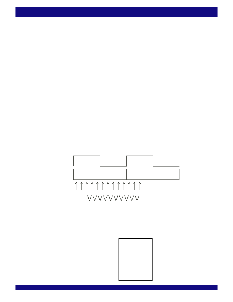
8.2.7 Software Eye-Opening Check on SPI-4
Interface
Since the SPI-4 interface is a DDR interface, both rising and falling edges
are used to update or sink data.
dn
dn+1
01
234567
89abc
c0
c5
c9
clock
data
over sample
position
counter
c1
c6
c4
c2
c7
c3
c8
6370 drw23b
Figure 33. DDR interface and eye opening check through over sampling
Refer to the IDT88P8344 uses an internal sampling clock cycle which has
afrequencyof10timesSPI-4clocktoover-samplethedataonalane.Foreach
sampling clock cycle t position n data are sampled and labeled as R
t.dn. The
following operation is then performed:
CNT
0= Rt.d2^ Rt.d3
CNT
1= Rt.d3^ Rt.d4
CNT
2= Rt.d4^ Rt.d5
CNT
3= Rt.d5^ Rt.d6
CNT
4= Rt.d6^ Rt.d7
CNT
5= Rt.d7^ Rt.d8
CNT
6= Rt.d8^ Rt.d9
CNT
7= Rt.d9^ Rt+1.d0
CNT
9= Rt+1.d0^ Rt+1.d1
相关PDF资料 |
PDF描述 |
|---|---|
| ESM44DRAS | CONN EDGECARD 88POS R/A .156 SLD |
| ASM28DSAS | CONN EDGECARD 56POS R/A .156 SLD |
| ESC60DRTN-S93 | CONN EDGECARD 120PS DIP .100 SLD |
| ESC60DRTH-S93 | CONN EDGECARD 120PS DIP .100 SLD |
| MIC5232-3.3YML TR | IC REG LDO 3.3V 10MA 6-MLF |
相关代理商/技术参数 |
参数描述 |
|---|---|
| IDT88P8344BHI | 功能描述:IC SPI3-SPI4 EXCHANGE 820-PBGA RoHS:否 类别:集成电路 (IC) >> 专用 IC 系列:* 产品培训模块:Lead (SnPb) Finish for COTS Obsolescence Mitigation Program 标准包装:1 系列:- 类型:调帧器 应用:数据传输 安装类型:表面贴装 封装/外壳:400-BBGA 供应商设备封装:400-PBGA(27x27) 包装:散装 |
| IDT89H10T4BG2ZBBC | 制造商:Integrated Device Technology Inc 功能描述:IC PCI SW 10LANE 4PORT 324BGA |
| IDT89H10T4BG2ZBBC8 | 制造商:Integrated Device Technology Inc 功能描述:IC PCI SW 10LANE 4PORT 324BGA |
| IDT89H10T4BG2ZBBCG | 功能描述:IC PCI SW 10LANE 4PORT 324BGA RoHS:是 类别:集成电路 (IC) >> 专用 IC 系列:PRECISE™ 产品培训模块:Lead (SnPb) Finish for COTS Obsolescence Mitigation Program 标准包装:1 系列:- 类型:调帧器 应用:数据传输 安装类型:表面贴装 封装/外壳:400-BBGA 供应商设备封装:400-PBGA(27x27) 包装:散装 |
| IDT89H10T4BG2ZBBCG8 | 制造商:Integrated Device Technology Inc 功能描述:IC PCI SW 10LANE 4PORT 324BGA |
发布紧急采购,3分钟左右您将得到回复。