参数资料
| 型号: | ADT7468ZEVB |
| 厂商: | ON Semiconductor |
| 文件页数: | 25/81页 |
| 文件大小: | 0K |
| 描述: | BOARD EVAL FOR ADT7468 |
| 标准包装: | 1 |
| 其它名称: | EVAL-ADT7468EB EVAL-ADT7468EB-ND |
第1页第2页第3页第4页第5页第6页第7页第8页第9页第10页第11页第12页第13页第14页第15页第16页第17页第18页第19页第20页第21页第22页第23页第24页当前第25页第26页第27页第28页第29页第30页第31页第32页第33页第34页第35页第36页第37页第38页第39页第40页第41页第42页第43页第44页第45页第46页第47页第48页第49页第50页第51页第52页第53页第54页第55页第56页第57页第58页第59页第60页第61页第62页第63页第64页第65页第66页第67页第68页第69页第70页第71页第72页第73页第74页第75页第76页第77页第78页第79页第80页第81页
�� �
�
�ADT7468�
�If� THERM� is� enabled� (Bit� 1,� Configuration� Register� 3� at�
�Address� 0x78):�
�THERM� Timer�
�?�
�Pin� 20� becomes� THERM.�
�The� ADT7468� has� an� internal� timer� to� measure� THERM�
�?� If� Pin� 14� is� configured� as� THERM� (Bit� 0� and� Bit� 1� of�
�Configuration� Register� 4� at� Address� 0x7D),� then� THERM�
�is� enabled� on� this� pin.�
�If� THERM� is� not� enabled:�
�?� Pin� 20� becomes� a� 5� V� measurement� input.�
�?� If� Pin� 14� is� configured� as� THERM,� then� THERM� is�
�disabled� on� this� Pin.�
�Table� 13.� Configuring� Pin� 14�
�Bit� 0� Bit� 1� Function�
�0� 0� TACH4�
�0� 1� THERM�
�1� 0� SMBALERT�
�assertion� time.� The� THERM� input� can� be� connected� to� the�
�PROCHOT� output� of� a� Pentium� 4� CPU� to� measure� system�
�performance� or� be� connected� to� the� output� of� a� trip� point�
�temperature� sensor,� to� name� a� couple� of� functions� of� the� timer.�
�The� timer� is� started� on� the� assertion� of� the� ADT7468’s� THERM�
�input� and� stopped� when� THERM� is� unasserted.� The� timer�
�counts� THERM� times� cumulatively,� that� is,� the� timer� resumes�
�counting� on� the� next� THERM� assertion.� The� THERM� timer�
�continues� to� accumulate� THERM� assertion� times� until� the�
�timer� is� read� (it� is� cleared� on� read)� or� until� it� reaches� full� scale.�
�If� the� counter� reaches� full� scale,� it� stops� at� that� reading� until�
�cleared.�
�1�
�1�
�GPIO�
�The� 8-bit� THERM� timer� register� (Reg.� 0x79)� is� designed� such�
�that� Bit� 0� is� set� to� 1� on� the� first� THERM� assertion.� Once� the�
�THERM� as� an� Input�
�When� THERM� is� configured� as� an� input,� the� user� can�
�time� assertions� on� the� THERM� pin.� This� can� be� useful� for�
�connecting� to� the� PROCHOT� output� of� a� CPU� to� gauge�
�system� performance.�
�The� user� can� also� set� up� the� ADT7468� to� run� the� fans� at� 100%�
�cumulative� THERM� assertion� time� has� exceeded� 45.52� ms,� Bit� 1�
�of� the� THERM� timer� is� set� and� Bit� 0� now� becomes� the� LSB� of�
�the� timer� with� a� resolution� of� 22.76� ms� (see� Figure� 31).�
�When� using� the� THERM� timer,� be� aware� of� the� following� after� a�
�THERM� timer� read� (Reg.� 0x79):�
�whenever� the� THERM� pin� is� driven� low� externally� by� setting�
�the� boost� bit� (Bit� 2)� in� Configuration� Register� 3� (Address� 0x78)�
�to� 1.� Note� that� to� set� this� up,� the� fan� must� be� already� running,�
�for� example,� in� manual� mode� when� the� current� duty� cycle� is�
�above� 0x00,� or� in� automatic� mode� when� the� temperature� is�
�1.�
�2.�
�The� contents� of� the� timer� are� cleared� on� read.�
�The� F4P� bit� (Bit� 5)� of Status� Register� 2� needs� to� be� cleared�
�(assuming� that� the� THERM� timer� limit� has� been�
�exceeded).�
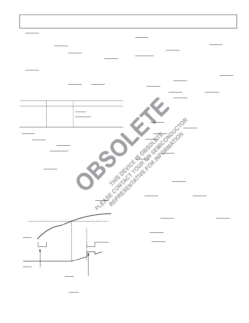
�above� T� MIN� .� If� the� temperature� is� below� T� MIN� or� i� f the dut� y� cycle�
�in� manual� mode� is� set� to� 0x00,� then� pulling� the� THERM� low�
�If� the� THERM� timer� is� read� during� a� THERM� assertion,� then�
�the� following� happens:�
�externally� has� no� effect.� See� Figure� 30� for� more� information.�
�T� MIN�
�THERM�
�1.�
�2.�
�3.�
�4.�
�The� contents� of� the� timer� are� cleared.�
�Bit� 0� of� the� THERM� timer� is� set� to� 1� (because� a� THERM�
�assertion� is� occurring).�
�The� THERM� timer� increments� from� 0.�
�If� the� THERM� timer� limit� (Reg.� 0x7A)� =� 0x00,� then� the�
�F4P� bit� is� set.�
�THERM� ASSERTED� TO� LOW� AS� AN� INPUT:�
�FANS� DO� NOT� GO� TO� 100%,� BECAUSE�
�TEMPERATURE� IS� BELOW� T� MIN�
�THERM� ASSERTED� TO� LOW� AS� AN� INPUT:�
�FANS� DO� NOT� GO� TO� 100%,� BECAUSE�
�TEMPERATURE� IS� ABOVE� T� MIN� AND� FANS�
�ARE� ALREADY� RUNNING�
�Figure� 30.� Asserting� THERM� Low� as� an� Input�
�in� Automatic� Fan� Speed� Control� Mode�
�Rev.� 3� |� Page� 25� of� 81� |� www.onsemi.com�
�相关PDF资料 |
PDF描述 |
|---|---|
| ADT7473ZEVB | BOARD EVALUATION FOR ADT7473 |
| ADT7475EBZEVB | BOARD EVALUATION FOR ADT7475 |
| ADT7476EBZEVB | BOARD EVALUATION FOR ADT7476 |
| ADT7490ZEVB | BOARD EVALUATION FOR ADT7490 |
| ADZS-21262-1-EZEXT | BOARD DAUGHTER FOR ADSP-21262 |
相关代理商/技术参数 |
参数描述 |
|---|---|
| ADT7470 | 制造商:AD 制造商全称:Analog Devices 功能描述:Temperature Sensor Hub and Fan Controller |
| ADT7470_13 | 制造商:AD 制造商全称:Analog Devices 功能描述:Temperature Sensor Hub and Fan Controller |
| ADT7470ARQ | 制造商:Analog Devices 功能描述:Temp Sensor Digital Serial (I2C) 16-Pin QSOP |
| ADT7470ARQ-REEL | 制造商:Rochester Electronics LLC 功能描述: 制造商:Analog Devices 功能描述: |
| ADT7470ARQ-REEL7 | 制造商:Analog Devices 功能描述:Temp Sensor Digital Serial (I2C) 16-Pin QSOP T/R |
发布紧急采购,3分钟左右您将得到回复。