- 您现在的位置:买卖IC网 > PDF目录69013 > M37274MA-XXXSP 8-BIT, MROM, MICROCONTROLLER, PDIP52 PDF资料下载
参数资料
| 型号: | M37274MA-XXXSP |
| 元件分类: | 微控制器/微处理器 |
| 英文描述: | 8-BIT, MROM, MICROCONTROLLER, PDIP52 |
| 封装: | 0.600 INCH, 1.778 MM PITCH, SHRINK, PLASTIC, DIP-52 |
| 文件页数: | 117/131页 |
| 文件大小: | 2049K |
| 代理商: | M37274MA-XXXSP |
第1页第2页第3页第4页第5页第6页第7页第8页第9页第10页第11页第12页第13页第14页第15页第16页第17页第18页第19页第20页第21页第22页第23页第24页第25页第26页第27页第28页第29页第30页第31页第32页第33页第34页第35页第36页第37页第38页第39页第40页第41页第42页第43页第44页第45页第46页第47页第48页第49页第50页第51页第52页第53页第54页第55页第56页第57页第58页第59页第60页第61页第62页第63页第64页第65页第66页第67页第68页第69页第70页第71页第72页第73页第74页第75页第76页第77页第78页第79页第80页第81页第82页第83页第84页第85页第86页第87页第88页第89页第90页第91页第92页第93页第94页第95页第96页第97页第98页第99页第100页第101页第102页第103页第104页第105页第106页第107页第108页第109页第110页第111页第112页第113页第114页第115页第116页当前第117页第118页第119页第120页第121页第122页第123页第124页第125页第126页第127页第128页第129页第130页第131页
86
SINGLE-CHIP 8-BIT CMOS MICROCOMPUTER with CLOSED CAPTION DECODER
and ON-SCREEN DISPLAY CONTROLLER
M37274MA-XXXSP
PRELIMINARY
Notice:
This
is not
a final
specification.
Some
paramentic
limits
are
subject
to change.
MITSUBISHI MICROCOMPUTERS
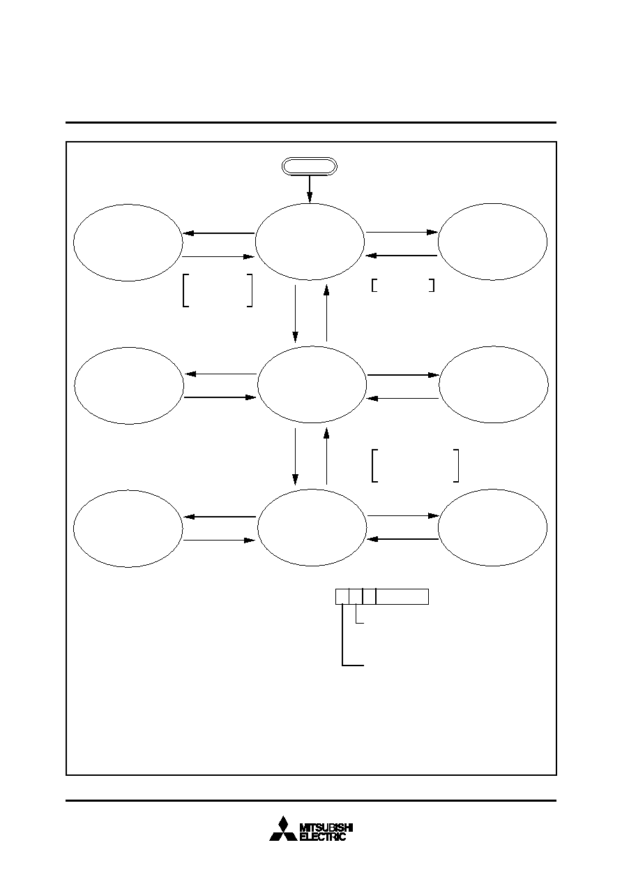
Fig. 98. State Transitions of System Clock
Reset
The example assumes that 8 MHz is being applied to the X IN pin and 32 kHz to the X CIN pin. The
φ indicates the internal clock.
WIT instruction
CM7 : Internal system clock selection bit
0 : XIN-XOUT selected (high-speed mode)
1 : XCIN-XCOUT selected (low-speed mode)
CPU mode register
(Address : 00FB16)
CM6 : Main clock (X IN–XOUT) stop bit
0 : Oscillating
1 : Stopped
8MHz oscillating
32kHz oscillating
φ is stopped (HIGH)
Timer operating
8MHz oscillating
32kHz oscillating
f(
φ) = 4MHz
8MHz stopped
32kHz stopped
φ is stopped (HIGH)
8MHz oscillating
32kHz oscillating
φ is stopped (HIGH)
Timer operating
(Note 3)
8MHz oscillating
32kHz oscillating
f(
φ) = 16kHz
8MHz stopped
32kHz stopped
φ is stopped (HIGH)
8MHz stopped
32kHz stopped
φ = stopped (HIGH )
8MHz stopped
32kHz oscillating
f(
φ) = 16kHz
8MHz stopped
32kHz oscillating
φ is stopped (HIGH)
Timer operating
(Note 3)
Interrupt
STP instruction
Interrupt (Note 1)
WIT instruction
Interrupt
WIT instruction
Interrupt
STP instruction
Interrupt (Note 2)
STP instruction
Interrupt (Note 2)
CM7 = 1
CM7 = 0
CM6 = 1
CM6 = 0
External INT,
timer interrupt,
or SI/O interrupt
External INT
Notes 1: When the STP state is ended, a delay of approximately 8ms is automatically generated by timer 3 and timer 4.
2: The delay after the STP state ends is approximately 2s.
3: When the internal clock
φ divided by 8 is used as the timer count source, the frequency of the count source is 2kHz.
The program must
allow time for 8MHz
oscillation to stabilize
High-speed operation
start mode
相关PDF资料 |
PDF描述 |
|---|---|
| M37373M8-XXXSP | 8-BIT, MROM, 8 MHz, MICROCONTROLLER, PDIP52 |
| M37409M2-XXXFP | 8-BIT, MROM, 10 MHz, MICROCONTROLLER, PQFP56 |
| M37413E6HXXXFP | 8-BIT, OTPROM, 8 MHz, MICROCONTROLLER, PQFP80 |
| M37413M4-XXXFP | 8-BIT, MROM, 8 MHz, MICROCONTROLLER, PQFP80 |
| M37420M4-XXXSP | 8-BIT, MROM, 8 MHz, MICROCONTROLLER, PDIP52 |
相关代理商/技术参数 |
参数描述 |
|---|---|
| M37276MF248SP | 制造商:MITSUBISHI 功能描述:* |
| M37276MF2575P | 制造商:MITSUBISHI 功能描述:* |
| M37276MF260SP | 制造商:MITSUBISHI 功能描述:* |
| M37276MF300SP | 制造商:MITSUBISHI 功能描述:* |
| M37276MF301SP | 制造商:MITSUBISHI 功能描述:* |
发布紧急采购,3分钟左右您将得到回复。