- 您现在的位置:买卖IC网 > PDF目录69013 > M37274MA-XXXSP 8-BIT, MROM, MICROCONTROLLER, PDIP52 PDF资料下载
参数资料
| 型号: | M37274MA-XXXSP |
| 元件分类: | 微控制器/微处理器 |
| 英文描述: | 8-BIT, MROM, MICROCONTROLLER, PDIP52 |
| 封装: | 0.600 INCH, 1.778 MM PITCH, SHRINK, PLASTIC, DIP-52 |
| 文件页数: | 57/131页 |
| 文件大小: | 2049K |
| 代理商: | M37274MA-XXXSP |
第1页第2页第3页第4页第5页第6页第7页第8页第9页第10页第11页第12页第13页第14页第15页第16页第17页第18页第19页第20页第21页第22页第23页第24页第25页第26页第27页第28页第29页第30页第31页第32页第33页第34页第35页第36页第37页第38页第39页第40页第41页第42页第43页第44页第45页第46页第47页第48页第49页第50页第51页第52页第53页第54页第55页第56页当前第57页第58页第59页第60页第61页第62页第63页第64页第65页第66页第67页第68页第69页第70页第71页第72页第73页第74页第75页第76页第77页第78页第79页第80页第81页第82页第83页第84页第85页第86页第87页第88页第89页第90页第91页第92页第93页第94页第95页第96页第97页第98页第99页第100页第101页第102页第103页第104页第105页第106页第107页第108页第109页第110页第111页第112页第113页第114页第115页第116页第117页第118页第119页第120页第121页第122页第123页第124页第125页第126页第127页第128页第129页第130页第131页
31
SINGLE-CHIP 8-BIT CMOS MICROCOMPUTER with CLOSED CAPTION DECODER
and ON-SCREEN DISPLAY CONTROLLER
M37274MA-XXXSP
PRELIMINARY
Notice:
This
is not
a final
specification.
Some
paramentic
limits
are
subject
to change.
MITSUBISHI MICROCOMPUTERS
VREF
256
! (n – 0.5)
1 to 255
0
Note: VREF indicates the voltage of internal VCC.
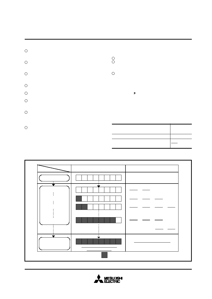
Fig. 23. Changes in A-D Conversion Register and Comparison Voltage during A-D Conversion
(6) Conversion Method
Set bit 7 of the interrupt input polarity register (address 021216) to
“1” to generate an interrupt request at completion of A-D conver-
sion.
Set the A-D conversion INT3 interrupt request bit to “0” (even
when A-D conversion is started, the A-D conversion INT3 inter-
rupt reguest bit is not set to “0” automatically).
When using A-D conversion interrupt, enable interrupts by setting
A-D conversion INT3 interrupt request bit to “1” and setting the
interrupt disable flag to “0.”
Set the VCC connection selection bit to “1” to connect VCC to the
resistor ladder.
Select analog input pins by the analog input selection bit of the A-
D control register.
Set the A-D conversion completion bit to “0.” This write operation
starts the A-D conversion. Do not read the A-D conversion regis-
ter during the A-D conversion.
Verify the completion of the conversion by the state (“1”) of the
A-D conversion completion bit, the state (“1”) of A-D conversion
INT3 interrupt reguest bit, or the occurrence of an A-D conversion
interrupt.
Read the A-D conversion register to obtain the conversion results.
Note : When the ladder resistor is disconnect from VCC, set the VCC
connection selection bit to “0” between steps 7and 8.
(7) Internal Operation
When the A-D conversion starts, the following operations are auto-
matically performed.
The A-D conversion register is set to “0016.”
The most significant bit of the A-D conversion register becomes
“1, ” and the comparison voltage “Vref” is input to the comparator.
At this point, Vref is compared with the analog input voltage “VIN .”
Bit 7 is determined by the comparison results as follows.
When Vref < VIN : bit 7 holds “1”
When Vref > VIN : bit 7 becomes “0”
With the above operations, the analog value is converted into a digi-
tal value. The A-D conversion terminates in a maximum of 50 ma-
chine cycles (12.5 s at f(XIN) = 8 MHz) after it starts, and the con-
version result is stored in the A-D conversion register.
An A-D conversion interrupt request occurs at the same time as A-D
conversion completion, the A-D conversion INT3 interrupt request
bit becomes “1.” The A-D conversion completion bit also becomes
“1.”
Table 3. Expression for Vref and VREF
A-D conversion register contents “n”
(decimal notation)
Vref (V)
12 3 45 6 7 8
1 00 0 0 0 0 0
12
10 0
0 0 0
10 0 0 0 0
0
1
12 3 4 5 6 7
1
VREF
2
VREF
512
–
VREF
2
VREF
4
VREF
512
–
±
VREF
2
VREF
4
VREF
8
VREF
512
–
±
00 0 0 0
00 0
Contents of A-D conversion register
Reference voltage (Vref)
[V]
0
A-D conversion start
1st comparison start
3rd comparison start
8th comparison start
2nd comparison start
Digital value corresponding to
analog input voltage.
A-D conversion completion
(8th comparison completion)
VREF
2
VREF
4
VREF
8
±
VREF
512
–
VREF
256
±
.......
: Value determined by mth (m = 1 to 8) result
m
.....
±
0
1
2
3
4
5
6
7
8
1
2
3
相关PDF资料 |
PDF描述 |
|---|---|
| M37373M8-XXXSP | 8-BIT, MROM, 8 MHz, MICROCONTROLLER, PDIP52 |
| M37409M2-XXXFP | 8-BIT, MROM, 10 MHz, MICROCONTROLLER, PQFP56 |
| M37413E6HXXXFP | 8-BIT, OTPROM, 8 MHz, MICROCONTROLLER, PQFP80 |
| M37413M4-XXXFP | 8-BIT, MROM, 8 MHz, MICROCONTROLLER, PQFP80 |
| M37420M4-XXXSP | 8-BIT, MROM, 8 MHz, MICROCONTROLLER, PDIP52 |
相关代理商/技术参数 |
参数描述 |
|---|---|
| M37276MF248SP | 制造商:MITSUBISHI 功能描述:* |
| M37276MF2575P | 制造商:MITSUBISHI 功能描述:* |
| M37276MF260SP | 制造商:MITSUBISHI 功能描述:* |
| M37276MF300SP | 制造商:MITSUBISHI 功能描述:* |
| M37276MF301SP | 制造商:MITSUBISHI 功能描述:* |
发布紧急采购,3分钟左右您将得到回复。