- 您现在的位置:买卖IC网 > PDF目录67684 > IBM37RGB524CF17A 1600 X 1280 PIXELS PALETTE-DAC DSPL CTLR, PQFP144 PDF资料下载
参数资料
| 型号: | IBM37RGB524CF17A |
| 元件分类: | 显示控制器 |
| 英文描述: | 1600 X 1280 PIXELS PALETTE-DAC DSPL CTLR, PQFP144 |
| 封装: | QFP-144 |
| 文件页数: | 6/72页 |
| 文件大小: | 509K |
| 代理商: | IBM37RGB524CF17A |
第1页第2页第3页第4页第5页当前第6页第7页第8页第9页第10页第11页第12页第13页第14页第15页第16页第17页第18页第19页第20页第21页第22页第23页第24页第25页第26页第27页第28页第29页第30页第31页第32页第33页第34页第35页第36页第37页第38页第39页第40页第41页第42页第43页第44页第45页第46页第47页第48页第49页第50页第51页第52页第53页第54页第55页第56页第57页第58页第59页第60页第61页第62页第63页第64页第65页第66页第67页第68页第69页第70页第71页第72页
8
March 17, 1995
RGB524
IBM
2.10
Direct Programming
Use the following steps to calculate the values used with
direct programming:
1.
Look up the REFCLK frequency in Table 5, "Direct
Programming Reference Divider Values," and write
the given programming value into the PLL
Reference Divider register (System PLL Reference
Divider for the SYSCLK PLL, Fixed Pixel PLL
Reference Divider for the pixel PLL). If the
incoming REFCLK frequency does not appear in
this table, then the direct programming method
cannot be used.
2.
to determine the values to write into the VCO
Divider register (System PLL VCO Divider for the
SYSCLK PLL, F0 - F15 for the pixel PLL). First,
pick the row of the table whose frequency range
covers the frequency of interest. This will determine
the value of the DF bits to write. Next, use the given
equation to calculate the value of the VCO DIV
BITS. Write these two values together to the
appropriate register.
The generated pixel clock frequency is designated in
this table as VF, for Video Frequency. Note that
within each range the desired VF frequency must
lie on a given step value (e.g., with DF = 11 a
frequency of 159 MHz is invalid because it does not
lie on a 2 MHz step; but either 158 MHz or 160 MHz
is valid).
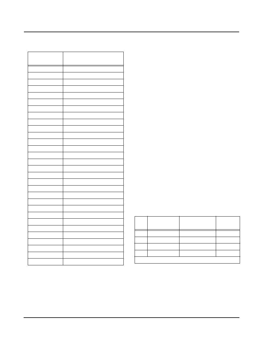
Table 5. Direct Programming Reference Divider Values
REFCLK (MHz)
Fixed PLL Reference Divider
Register Value
4
0x0002
6
0x0003
8
0x0004
10
0x0005
12
0x0006
14
0x0007
16
0x0008
18
0x0009
20
0x000a
22
0x000b
24
0x000c
26
0x000d
28
0x000e
30
0x000f
32
0x0010
34
0x0011
36
0x0012
38
0x0013
40
0x0014
42
0x0015
44
0x0016
46
0x0017
48
0x0018
50
0x0019
52
0x001a
54
0x001b
56
0x001c
58
0x001d
60
0x001e
62
0x001f
Table 6. PLL Direct Programming Equations
DF
VCO Divide
Count
Frequency Range Step (MHz)
00
(4 x VF) - 65
16.25 - 32 MHz
0.25
01
(2 x VF) - 65
32.5 - 64 MHz
0.5
10
VF - 65
65.0 - 128 MHz
1.0
11
(VF / 2) - 65
130.0 - 220 MHz
2.0
VF = Desired Video Frequency
相关PDF资料 |
PDF描述 |
|---|---|
| IC-WT-SO16N | ROTARY/LINEAR OPTICAL POSITION ENCODER |
| ICD2028SCR-5 | 100 MHz, PROC SPECIFIC CLOCK GENERATOR, PDSO20 |
| ICD2063SC-1 | 135 MHz, VIDEO CLOCK GENERATOR, PDSO16 |
| ICD2063SC-2 | 135 MHz, VIDEO CLOCK GENERATOR, PDSO16 |
| ICD2063SC-3 | 135 MHz, VIDEO CLOCK GENERATOR, PDSO16 |
相关代理商/技术参数 |
参数描述 |
|---|---|
| IBM37RGB524CF22A | 制造商:未知厂家 制造商全称:未知厂家 功能描述:Video DAC with Color Palette (RAMDAC) |
| IBM39ENV422DLL00C | 制造商:IBM 功能描述: |
| IBM39ENV422PBA17C | 制造商:IBM Microelectronics 功能描述:VID ENCODER 420PIN HPBGA - Trays 制造商:IBM 功能描述:IBM IBM39ENV422PBA17C Encoders - Decoders |
| IBM39MPEGCD20PFD22C | 制造商:IBM 功能描述: |
| IBM39MPEGCS22PFJ22C | 制造商:IBM 功能描述: |
发布紧急采购,3分钟左右您将得到回复。