- 您现在的位置:买卖IC网 > PDF目录295917 > EWIXP455ABT (INTEL CORP) 266 MHz, RISC PROCESSOR, PBGA544 PDF资料下载
参数资料
| 型号: | EWIXP455ABT |
| 厂商: | INTEL CORP |
| 元件分类: | 微控制器/微处理器 |
| 英文描述: | 266 MHz, RISC PROCESSOR, PBGA544 |
| 封装: | LEAD FREE, PLASTIC, BGA-544 |
| 文件页数: | 56/163页 |
| 文件大小: | 1123K |
| 代理商: | EWIXP455ABT |
第1页第2页第3页第4页第5页第6页第7页第8页第9页第10页第11页第12页第13页第14页第15页第16页第17页第18页第19页第20页第21页第22页第23页第24页第25页第26页第27页第28页第29页第30页第31页第32页第33页第34页第35页第36页第37页第38页第39页第40页第41页第42页第43页第44页第45页第46页第47页第48页第49页第50页第51页第52页第53页第54页第55页当前第56页第57页第58页第59页第60页第61页第62页第63页第64页第65页第66页第67页第68页第69页第70页第71页第72页第73页第74页第75页第76页第77页第78页第79页第80页第81页第82页第83页第84页第85页第86页第87页第88页第89页第90页第91页第92页第93页第94页第95页第96页第97页第98页第99页第100页第101页第102页第103页第104页第105页第106页第107页第108页第109页第110页第111页第112页第113页第114页第115页第116页第117页第118页第119页第120页第121页第122页第123页第124页第125页第126页第127页第128页第129页第130页第131页第132页第133页第134页第135页第136页第137页第138页第139页第140页第141页第142页第143页第144页第145页第146页第147页第148页第149页第150页第151页第152页第153页第154页第155页第156页第157页第158页第159页第160页第161页第162页第163页
Electrical Specifications
Intel IXP45X and Intel IXP46X Product Line of Network Processors Datasheet
May 2005
Document Number: 306261-002
149
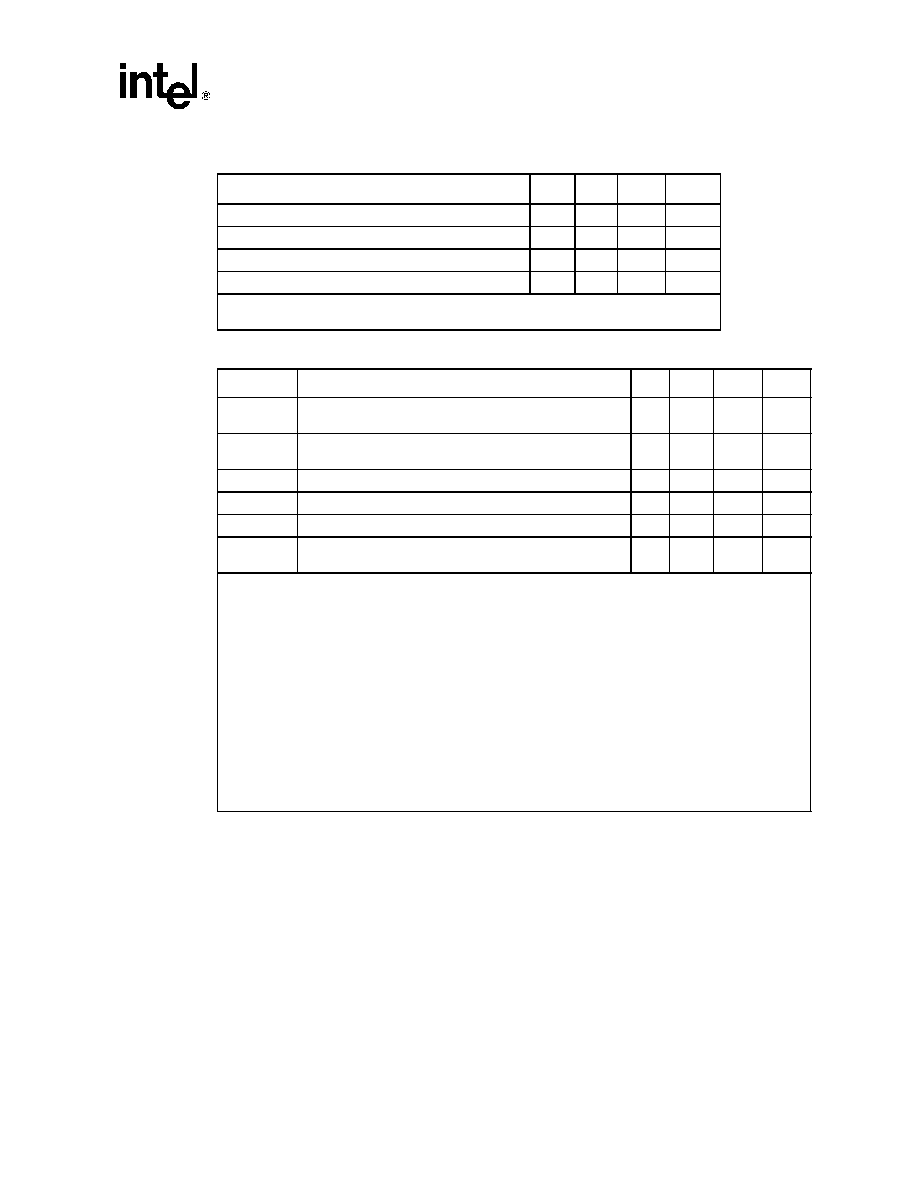
Table 72.
Setup/Hold Timing Values in Asynchronous Mode of Operation
Parameter
Min.
Max.
Units
Notes
Output Valid after rising edge of EX_CLK
10
ns
1
Output Hold after rising edge of EX_CLK
0
ns
1
Input Setup prior to rising edge of EX_CLK
3.5
ns
1
Input Hold required after rising edge of EX_CLK
0.5
ns
1
NOTES:
1. The Setup and Hold Timing values are for all modes.
Table 73.
HPI*-16 Multiplexed Write Accesses Values
Symbol
Parameter
Min.
Max.
Units
Notes
Tadd_setup
Valid time that address is asserted on the line. The address
is asserted at the same time as chip select.
11
45
Cycles 1, 5, 6
Tcs2hds1val
Delay from chip select being active and the HDS1 data
strobe being active.
3
4
Cycles 5, 6
Thds1_pulse
Pulse width of the HDS1 data strobe
4
5
Cycles 2, 4, 5
Tdata_setup
Data valid prior to the rising edge of the HDS1 data strobe.
4
5
Cycles 3, 5, 6
Tdata_hold
Data valid after the rising edge of the HDS1 data strobe.
4
36
Cycles 3, 6
Trecov
Time required between successive accesses on the
expansion interface.
217
Cycles 4, 6
NOTES:
1. The address phase parameter (T1) must be set to a minimum value of 2. This value allows three T clocks
for the address phase. This setting is required to ensure that in the event of an HRDY, the IXP45X/IXP46X
network processors have had sufficient time to recognize the HRDY and hold the address phase for at
least one clock pulse after the HRDY is de-active.
2. The data setup phase parameter (T2) must be set to a minimum value of 2. This value allows three T
clocks for setup phase.
3. The data strobe phase parameter (T3) must be set to a minimum value of 1. This value allows two T clocks
for the data phase. This setting is required to ensure that in the event of an HRDY, the IXP45X/IXP46X
network processors have had sufficient time to recognize the HRDY and hold the data setup phase for at
least one clock pulse after the HRDY is de-active
4. Setting the recovery phase parameter (T5) will adjust the duration between successive accesses on the
Expansion Bus interface.
5. HRDY can be asserted by the DSP at any point in the access. The interface will not leave states T1 or T3
until HRDY is de-active
6. One cycle is the period of the Expansion Bus clock.
7. Timing was designed for a system load between 5pF and 60pF for high drive setting
相关PDF资料 |
PDF描述 |
|---|---|
| EX5-R-PL | 16 CONTACT(S), MALE, COMBINATION LINE CONNECTOR, SOLDER |
| EXH2E106HR | PLASTIC FILM CAPACITORS |
| EXH2E205HR | PLASTIC FILM CAPACITORS |
| EXH2E255HR | PLASTIC FILM CAPACITORS |
| EXH2E305HR | PLASTIC FILM CAPACITORS |
相关代理商/技术参数 |
参数描述 |
|---|---|
| EWIXP455BAC | 制造商:Rochester Electronics LLC 功能描述:- Bulk |
| EWIXP460BAD | 制造商:Rochester Electronics LLC 功能描述:- Bulk 制造商:Intel 功能描述: |
| EWJKXA066A15 | 制造商:Panasonic Industrial Company 功能描述:CONTROL |
| EWK105BJ224MP-F | 制造商:TAIYO YUDEN 功能描述:Cut Tape 制造商:Taiyo Yuden 功能描述:Ceramic capacitor LWDC 0402 220nF 制造商:Taiyo Yuden 功能描述:Cap Ceramic 0.22uF 16V X5R 20% SMD 0204 85 制造商:Taiyo Yuden 功能描述:Cap Ceramic 0.22uF 16V X5R 20% SMD 0204 85°C Paper T/R |
| EWK105BJ224MPHF | 功能描述:CAP CER 0.22UF 16V X5R 0204 制造商:taiyo yuden 系列:LWDC?,LW 包装:剪切带(CT) 零件状态:在售 电容:0.22μF 容差:±20% 电压 - 额定:16V 温度系数:X5R 工作温度:-55°C ~ 85°C 特性:低 ESL 型(倒置结构) 等级:AEC-Q200 应用:汽车,旁通,去耦 故障率:- 安装类型:表面贴装,MLCC 封装/外壳:0204(0610 公制) 大小/尺寸:0.020" 长 x 0.039" 宽(0.52mm x 1.00mm) 高度 - 安装(最大值):- 厚度(最大值):0.014"(0.35mm) 引线间距:- 引线形式:- 标准包装:1 |
发布紧急采购,3分钟左右您将得到回复。