- 您现在的位置:买卖IC网 > PDF目录67592 > FUSION878A (CONEXANT SYSTEMS) COLOR SIGNAL DECODER, PQFP128 PDF资料下载
参数资料
| 型号: | FUSION878A |
| 厂商: | CONEXANT SYSTEMS |
| 元件分类: | 颜色信号转换 |
| 英文描述: | COLOR SIGNAL DECODER, PQFP128 |
| 封装: | PLASTIC, QFP-128 |
| 文件页数: | 10/180页 |
| 文件大小: | 2067K |
| 代理商: | FUSION878A |
第1页第2页第3页第4页第5页第6页第7页第8页第9页当前第10页第11页第12页第13页第14页第15页第16页第17页第18页第19页第20页第21页第22页第23页第24页第25页第26页第27页第28页第29页第30页第31页第32页第33页第34页第35页第36页第37页第38页第39页第40页第41页第42页第43页第44页第45页第46页第47页第48页第49页第50页第51页第52页第53页第54页第55页第56页第57页第58页第59页第60页第61页第62页第63页第64页第65页第66页第67页第68页第69页第70页第71页第72页第73页第74页第75页第76页第77页第78页第79页第80页第81页第82页第83页第84页第85页第86页第87页第88页第89页第90页第91页第92页第93页第94页第95页第96页第97页第98页第99页第100页第101页第102页第103页第104页第105页第106页第107页第108页第109页第110页第111页第112页第113页第114页第115页第116页第117页第118页第119页第120页第121页第122页第123页第124页第125页第126页第127页第128页第129页第130页第131页第132页第133页第134页第135页第136页第137页第138页第139页第140页第141页第142页第143页第144页第145页第146页第147页第148页第149页第150页第151页第152页第153页第154页第155页第156页第157页第158页第159页第160页第161页第162页第163页第164页第165页第166页第167页第168页第169页第170页第171页第172页第173页第174页第175页第176页第177页第178页第179页第180页
Fusion 878A
3.0 Electrical Interfaces
PCI Video Decoder
3.5 I2C Serial EEPROM Interface
100600B
Conexant
3-23
3.5 I2C Serial EEPROM Interface
The external EEPROM must reside on the I2C bus (SDA, SCL). This interface
supports the IC’s equivalent to the 24C02 or 24C02A 2 k bit 5 V CMOS Serial
EEPROM. The 7-bit slave device address is 1010000. The EEPROM can be read
anytime using the I2C hardware or software modes. The read transaction
sequence is:
1.
START
2.
0xA0
3.
8-bit byte address
4.
START
5.
0xA1
6.
8-bit read data, followed by (master NACK &) STOP
Thus, a normal 2-byte write transaction without STOP followed by a 2-byte
read transaction allows random access to a data byte.
3.5.1 EEPROM Address Mapping
Fusion 878A can support one EEPROM (max 256 B), typically a single 24C02.
Re-map the 8-bit addressable physical memory space to an 8-bit logical address
space by inverting the address A[7:0], and subtracting 4. The 7-bit slave device
address is 1010_xxx where the xxx bits are (normally used for A[10:8]) set to
zero. The A2, A1, A0 pins on the 24C02 device should be tied low to match.
Re-mapping the address space in this way allows the subsystem IDs to be
stored at a fixed physical base address and have the read-only section precede the
read-writable section. The entire address range (rather than some sub-portion) is
inverted to maintain physical address continuity. The address translation applies
only when the hardware accesses subsystem IDs or vital product data. If SW uses
the I2C function to directly address the EEPROM, the actual physical address
must be used.
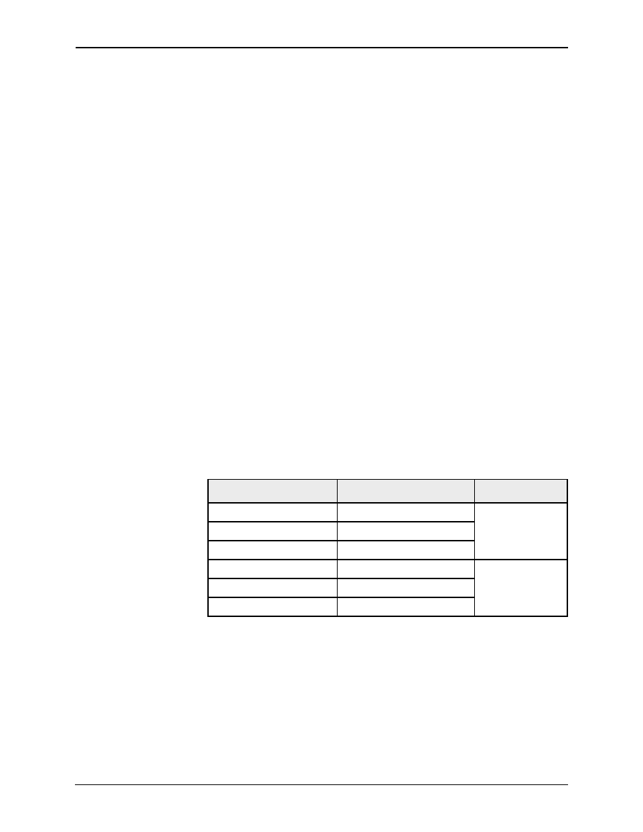
Table 3-6. External EEPROM Memory Map
Logical Address
Physical Address
24C02
251
0x00
Read/Write
...
124
0x7F
123
0x80
Read-Only
...
–40xFF
相关PDF资料 |
PDF描述 |
|---|---|
| FVXO-HC53BR-FREQ | VCXO, CLOCK, 0.75 MHz - 250 MHz, HCMOS OUTPUT |
| FVXO-HC72BR-FREQ | VCXO, CLOCK, 0.75 MHz - 180 MHz, HCMOS OUTPUT |
| FVXO-HC73B-FREQ | VCXO, CLOCK, 0.75 MHz - 250 MHz, HCMOS OUTPUT |
| FVXO-LC52BR-FREQ | VCXO, CLOCK, 0.75 MHz - 1000 MHz, LVDS OUTPUT |
| FVXO-LC72BR-FREQ | VCXO, CLOCK, 0.75 MHz - 1000 MHz, LVDS OUTPUT |
相关代理商/技术参数 |
参数描述 |
|---|---|
| FUSZ03 | 制造商:Honeywell Sensing and Control 功能描述: |
| FUTURE 1AA PLUS | 制造商:Ansmann 功能描述: 制造商:ANSMANN AG 功能描述: |
| FUTURE 2AA PLUS | 制造商:Ansmann 功能描述: 制造商:ANSMANN AG 功能描述: |
| FUTURE 2C PLUS | 制造商:Ansmann 功能描述: 制造商:ANSMANN AG 功能描述: |
| FUTURE 3D PLUS | 制造商:Ansmann 功能描述: 制造商:ANSMANN AG 功能描述: |
发布紧急采购,3分钟左右您将得到回复。