- 您现在的位置:买卖IC网 > PDF目录67592 > FUSION878A (CONEXANT SYSTEMS) COLOR SIGNAL DECODER, PQFP128 PDF资料下载
参数资料
| 型号: | FUSION878A |
| 厂商: | CONEXANT SYSTEMS |
| 元件分类: | 颜色信号转换 |
| 英文描述: | COLOR SIGNAL DECODER, PQFP128 |
| 封装: | PLASTIC, QFP-128 |
| 文件页数: | 125/180页 |
| 文件大小: | 2067K |
| 代理商: | FUSION878A |
第1页第2页第3页第4页第5页第6页第7页第8页第9页第10页第11页第12页第13页第14页第15页第16页第17页第18页第19页第20页第21页第22页第23页第24页第25页第26页第27页第28页第29页第30页第31页第32页第33页第34页第35页第36页第37页第38页第39页第40页第41页第42页第43页第44页第45页第46页第47页第48页第49页第50页第51页第52页第53页第54页第55页第56页第57页第58页第59页第60页第61页第62页第63页第64页第65页第66页第67页第68页第69页第70页第71页第72页第73页第74页第75页第76页第77页第78页第79页第80页第81页第82页第83页第84页第85页第86页第87页第88页第89页第90页第91页第92页第93页第94页第95页第96页第97页第98页第99页第100页第101页第102页第103页第104页第105页第106页第107页第108页第109页第110页第111页第112页第113页第114页第115页第116页第117页第118页第119页第120页第121页第122页第123页第124页当前第125页第126页第127页第128页第129页第130页第131页第132页第133页第134页第135页第136页第137页第138页第139页第140页第141页第142页第143页第144页第145页第146页第147页第148页第149页第150页第151页第152页第153页第154页第155页第156页第157页第158页第159页第160页第161页第162页第163页第164页第165页第166页第167页第168页第169页第170页第171页第172页第173页第174页第175页第176页第177页第178页第179页第180页
Fusion 878A
2.0 Functional Description
PCI Video Decoder
2.9 VBI Data Output Interface
100600B
Conexant
2-25
The Fusion 878A is able to capture VBI data and store it in the host memory
for later processing by the Fusion 878A VBI decoder software. Two modes of
VBI capture exist: VBI line output mode and VBI frame output mode. Both types
of data may be captured during the same field.
2.9.1 VBI Line Output Mode
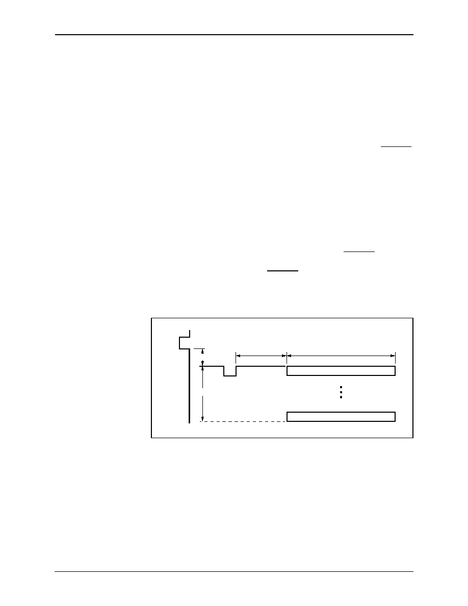
In the VBI line output mode, VBI capture occurs during the vertical blanking
interval. The start of VBI data capture is set by the VBI_HDELAY bit in the VBI
Packet Size/Delay register, and is in reference to the trailing edge of the HRESET
signal. The number of DWORDs of VBI data is selected by the user. Each
DWORD contains 4 VBI bytes, and each VBI pixel consists of two VBI samples.
For example, for a given 800 pixel line in the VBI region, there exist 1600 VBI
samples, which are equivalent to 400 DWORDs of VBI data. The VBI_PKT_HI
and VBI_PKT_LO register bits are concatenated to create the 9-bit value for the
number of DWORDs to be captured.
VBI line data capture occurs when the CAPTURE_VBI_EVEN register bit is
enabled for the even field, and CAPTURE_VBI_ODD register bit is enabled for
the odd field. The VBI data is sampled at a rate of 8 × Fsc and is stored in the
FIFO as a sequence of 8-bit samples. Line mode VBI data starts horizontally
beginning at VBI_HDELAY pixels from the trailing edge of HRESET and ending
after the VBI_PKT number of DWORDs. Line mode VBI data starts vertically
beginning at the first line following VRESET and ending at VACTIVE. VBI
register settings can be changed only on a per-frame basis. The VBI timing is
illustrated in Figure 2-17.
Once the VBI data has been captured and stored in the Fusion 878A FIFO, it is
treated as any other type of data. It is output over the PCI bus via RISC
instructions. If the number of VBI lines desired by the user is smaller than the
entire vertical blanking region, the extra data will be discarded by the use of the
SKIP RISC instruction. Alternatively, if the user desires a larger VBI region in the
VBI line output mode, the vertical blanking region can be extended by setting the
VDELAY register to the appropriate value. The VBI line output mode can in
effect extend the VBI region to the entire field. Figure 2-18 illustrates a block
diagram of the VBI section.
Figure 2-17. VBI Timing
VBI Line Data Capture
VBI_PKT #
VBI_HDELAY
VACTIVE
VRESET
HRESET
VDELAY
879A_022
相关PDF资料 |
PDF描述 |
|---|---|
| FVXO-HC53BR-FREQ | VCXO, CLOCK, 0.75 MHz - 250 MHz, HCMOS OUTPUT |
| FVXO-HC72BR-FREQ | VCXO, CLOCK, 0.75 MHz - 180 MHz, HCMOS OUTPUT |
| FVXO-HC73B-FREQ | VCXO, CLOCK, 0.75 MHz - 250 MHz, HCMOS OUTPUT |
| FVXO-LC52BR-FREQ | VCXO, CLOCK, 0.75 MHz - 1000 MHz, LVDS OUTPUT |
| FVXO-LC72BR-FREQ | VCXO, CLOCK, 0.75 MHz - 1000 MHz, LVDS OUTPUT |
相关代理商/技术参数 |
参数描述 |
|---|---|
| FUSZ03 | 制造商:Honeywell Sensing and Control 功能描述: |
| FUTURE 1AA PLUS | 制造商:Ansmann 功能描述: 制造商:ANSMANN AG 功能描述: |
| FUTURE 2AA PLUS | 制造商:Ansmann 功能描述: 制造商:ANSMANN AG 功能描述: |
| FUTURE 2C PLUS | 制造商:Ansmann 功能描述: 制造商:ANSMANN AG 功能描述: |
| FUTURE 3D PLUS | 制造商:Ansmann 功能描述: 制造商:ANSMANN AG 功能描述: |
发布紧急采购,3分钟左右您将得到回复。