参数资料
| 型号: | HW-XGI-VIDEO-US |
| 厂商: | Xilinx Inc |
| 文件页数: | 36/68页 |
| 文件大小: | 0K |
| 描述: | DAUGHTER CARD VIDEO I/O VIODC |
| 标准包装: | 1 |
| 其它名称: | 122-1506 HW-XGI-VIDEO-US-ND |
第1页第2页第3页第4页第5页第6页第7页第8页第9页第10页第11页第12页第13页第14页第15页第16页第17页第18页第19页第20页第21页第22页第23页第24页第25页第26页第27页第28页第29页第30页第31页第32页第33页第34页第35页当前第36页第37页第38页第39页第40页第41页第42页第43页第44页第45页第46页第47页第48页第49页第50页第51页第52页第53页第54页第55页第56页第57页第58页第59页第60页第61页第62页第63页第64页第65页第66页第67页第68页
�� �
�
�Chapter� 4:� DVI/VGA� Input� Interface�
�R�
�The� HSYNC� and� VSYNC� signals� are� critical� to� the� VGA� interface,� but� can� be� encoded� in�
�several� ways.� The� most� basic� is� with� separate� sync� signals� for� each,� increasing� the� number�
�of� signals� to� 5:� RGBHV.� These� syncs� can� be� active� high� or� low,� and� different� resolutions�
�typically� have� different� combinations� of� sync� polarity.� A� second� encoding� is� composite� HV,�
�with� HSYNC� and� VSYNC� combined� onto� a� single� signal.� This� is� preformed� through� a�
�logical� XOR� of� the� two� signals.� The� end� result� looks� like� the� original� HSYNC� signal,� except�
�that� its� polarity� is� inverted� during� VSYNC.� This� mode� reduces� the� number� of� signals� to� 4.�
�A� third� mode� of� encoding� the� sync� signals� is� by� combining� the� composite� sync� signal� with�
�the� green� data.� This� is� referred� to� as� “sync-on-green”� (SOG).� As� mentioned� previously,� the�
�typical� signal� levels� are� 0-700mV.� SOG� offsets� this� by� 300mV� to� 300mV-1V.� The� drop� from�
�300mV� to� 0� is� used� to� indicate� the� composite� sync.�
�Table� 4-1:� VGA� Standards�
�Pix�
�Clock�
�Freq�
�(MHz)�
�HSync�
�Freq�
�(kHz)�
�Front�
�Porch�
�Horizontal� Timings�
�(in� clk� cycles)�
�Back�
�Sync�
�Porch�
�Active�
�Front�
�Porch�
�Vertical� Timings�
�(in� Lines)�
�Back�
�Sync�
�Porch�
�Active�
�VGA60�
�XGA60�
�SXGA60�
�UXGA60�
�40�
�65�
�108�
�162�
�37.9�
�48.4�
�64�
�75�
�40�
�24�
�48�
�64�
�128�
�136�
�112�
�192�
�88�
�160�
�248�
�304�
�800�
�1024�
�1280�
�1600�
�1�
�3�
�1�
�1�
�4�
�6�
�3�
�3�
�23�
�29�
�38�
�46�
�600�
�768�
�1024�
�1200�
�Setting� the� PLL� and� Phase�
�The� AD9887A� digitizes� the� analog� video� waveforms� using� three� 8-bit� analog-to-digital�
�converters.� For� this� analog-to-digital� conversion� to� operate� properly,� it� must� sample� each�
�pixel� at� the� appropriate� time� (� Figure� 4-4� ).�
�1 1�
�2�
�12� Active� Pixels�
�1 1�
�2�
�RGB�
�10�
�11�
�0�
�1�
�2�
�3�
�4�
�5�
�6�
�7�
�8�
�9�
�10�
�11�
�0�
�HSYNC�
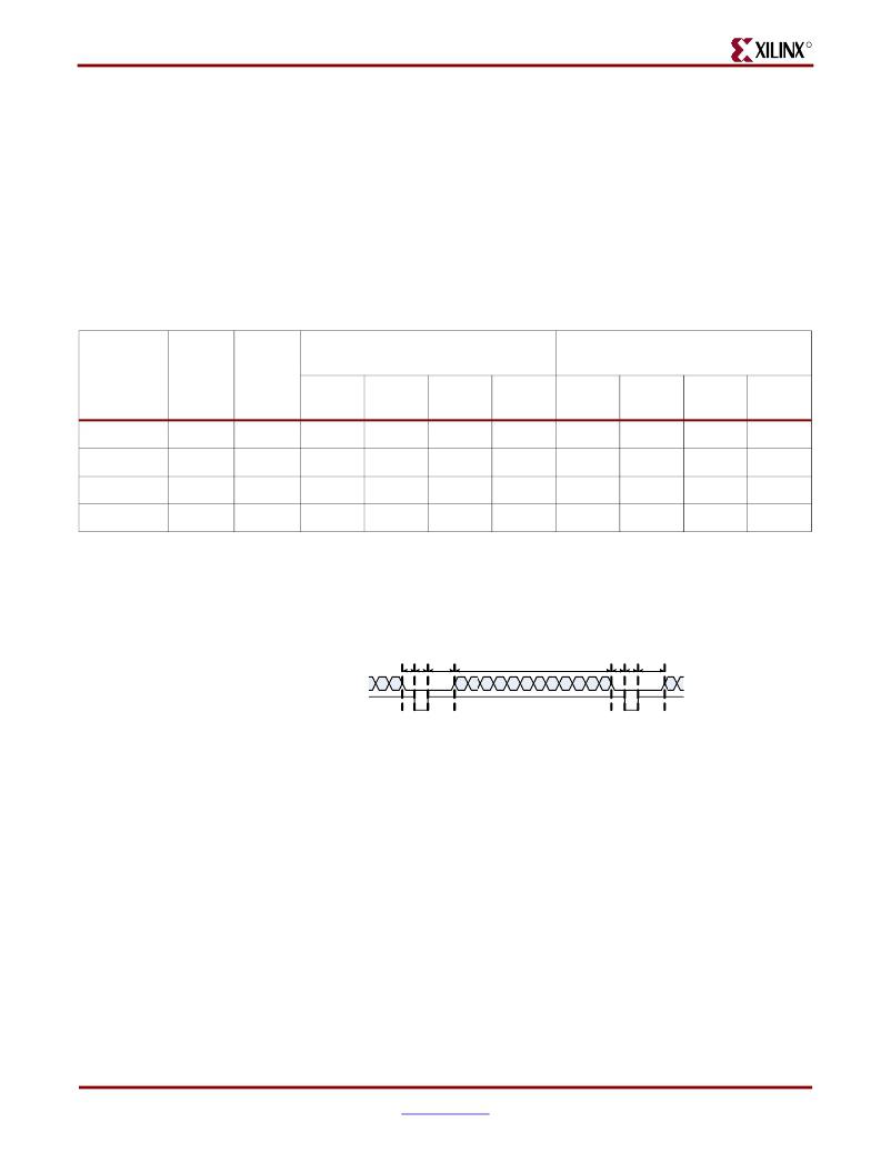
�Figure� 4-4:� Pixel� Sampling�
�To� explain� VGA� sampling� theory,� it� is� useful� to� use� a� greatly� simplified� example.� Figure 4-4�
�shows� a� single� line� from� a� frame� with� the� horizontal� front� porch� set� to� 1,� the� sync� length� set�
�to� 1,� and� the� horizontal� back� porch� set� to� 2.� The� line� has� 12� active� pixels.� In� order� to� receive�
�the� video� data,� these� are� the� only� signals� available.�
�Figure� 4-5� illustrates� the� ideal� ADC� sampling� positions� for� this� line.� To� generate� these�
�sample� times,� the� AD9887A� includes� a� PLL� that� locks� to� the� incoming� HSYNC,�
�multiplying� the� HSYNC� frequency� by� a� factor� set� by� the� feedback� divider.� The� frequency�
�multiplication� factor� is� set� to� the� total� number� of� clock� cycles� per� HSYNC� period.� For� the�
�Figure� 4-5� example,� the� multiplication� value� is� 1+1+2+12� =� 16.� The� PLL� in� the� AD9887A� is�
�free-running,� so� ADC� samples� occur� during� blanking� (gray� arrows)� as� well� as� active� video�
�36�
��Video� Input/Output� Daughter� Card�
�UG235� (v1.2.1)� October� 31,� 2007�
�相关PDF资料 |
PDF描述 |
|---|---|
| ICD15S13E6GV00LF | CONN DSUB HD SOCKT 15POS R/A PCB |
| ICD26S13E4GX00LF | CONN DSUB HD SOCKT 26POS R/A PCB |
| ID09S33E4GV00LF | CONN RCPT 9POS R/A GOLD |
| ID451000 | CONN RECPT USB A ADAPTER |
| IELHK11-1-72-70.0-01-V | CIRCUIT BREAKER HYMAG DP 70A |
相关代理商/技术参数 |
参数描述 |
|---|---|
| HWXX35338TR | 制造商:Vishay Intertechnologies 功能描述: |
| HWXX38438 | 制造商:Vishay Semiconductors 功能描述: |
| HWZ1408 | 制造商:OHIO BUCKEYE 功能描述: |
| HWZ1424 | 制造商:OHIO BUCKEYE 功能描述: |
| HWZ1620 | 制造商:OHIO BUCKEYE 功能描述: |
发布紧急采购,3分钟左右您将得到回复。