- 您现在的位置:买卖IC网 > PDF目录67685 > ICS1890Y-14 1 CHANNEL(S), 100M bps, SERIAL COMM CONTROLLER, PQFP64 PDF资料下载
参数资料
| 型号: | ICS1890Y-14 |
| 元件分类: | 微控制器/微处理器 |
| 英文描述: | 1 CHANNEL(S), 100M bps, SERIAL COMM CONTROLLER, PQFP64 |
| 封装: | TQFP-64 |
| 文件页数: | 41/66页 |
| 文件大小: | 1749K |
| 代理商: | ICS1890Y-14 |
第1页第2页第3页第4页第5页第6页第7页第8页第9页第10页第11页第12页第13页第14页第15页第16页第17页第18页第19页第20页第21页第22页第23页第24页第25页第26页第27页第28页第29页第30页第31页第32页第33页第34页第35页第36页第37页第38页第39页第40页当前第41页第42页第43页第44页第45页第46页第47页第48页第49页第50页第51页第52页第53页第54页第55页第56页第57页第58页第59页第60页第61页第62页第63页第64页第65页第66页
46
ICS1890
Phy Address 4 - Receive Data LED
P4RD
At power-up and reset, this pin is sampled for a logic high or
zero. If a logic one is detected, a value of 16 is set in the
configuration register.
The ICS1890 sets this bit to the appropriate value to turn on
the LED when receive data is detected. This signal is stretched
ensure that a single packet will be seen. If the packet stream
is continuous, the LED will appear permanently on.
Phy Address 3 - Transmit Data LED
P3TD
At power-up and reset, this pin is sampled for a logic high or
zero. If a logic one is detected, a value of 8 is set in the
configuration register.
The ICS1890 sets this bit to the appropriate value to turn on
the LED when transmit data is detected. This signal is stretched
to ensure that a single packet will be seen. If the packet stream
is continuous, the LED will appear permanently on.
Phy Address 2 - Link Integrity LED
P2LI
At power-up and reset, this pin is sampled for a logic high or
zero. If a logic one is detected, a value of 4 is set in the
configuration register.
The ICS1890 sets this bit to the appropriate value to turn on
the LED when the Link Integrity status is OK.
Phy Address 1 - Collision LED
P1CL
At power-up and reset, this pin is sampled for a logic high or
zero. If a logic one is detected, a value of 2 is set in the
configuration register.
The ICS1890 sets this bit to the appropriate value to turn on
the LED when a collision is detected. This signal is stretched
to ensure that a single collision will be seen. If the collisions
are continuous, the LED will appear permanently on.
Phy Address 0 - Activity LED
P0AC
At power-up and reset, this pin is sampled for a logic high or
zero. If a logic one is detected, a value of 1 is set in the
configuration register.
The ICS1890 sets this bit to the appropriate value to turn on
the LED when either transmit or receive activity is detected.
This signal is stretched to ensure that a single activity event
will be seen. If the activity is continuous, the LED will appear
permanently on.
Power Supply
These 7 VDD and 8 VSS pins supply power to theICS1890 device.
ICS1890 Power Supply Isolation and Filtering
It is important to properly isolate the ICS1890 10/100Base-
TX Physical Layer Device from noise sources in a system
design. There are two key areas to consider, isolation from
digital noise and noise coupling between the transmitter and
receiver.
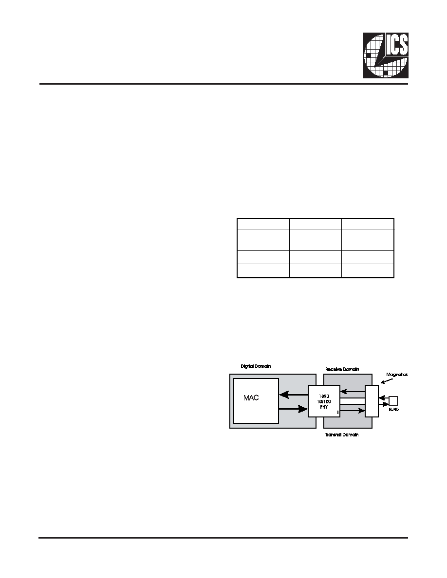
Filtering for the ICS1890 is accomplished by separating the
power supply into three domains: digital, transmit, and receive.
All supply pins on the device fall into one of these three
categories as shown in the table below.
In the above table, each supply pin is followed directly by its
ground pin. Each supply pair should be bypassed with a 0.1F
capacitor located as close to the device as possible.
The PCB board may have separate power and ground planes
for the ICS1890. The power planes could be split into three
domains following the pin isolation. A single, uniform plane
should be used for ground. Power plane placement is illustrated
in the figure below.
Point-to-point trace routing for power connections may be
used instead of actual power planes if required by printed
circuit board constraints.
Both the Receive andTransmit Domains should be connected
to the Digital Domain or main supply through a ferrite bead or
inductor,withavalueof.1Hto1H.Thebestfilterconfiguration
is a pi filter composed of a .1H capacitor, .1H ferrite bead,
and a .1H capacitor at the device pin.
Reserved & N/C Pins
Four pins are labeled Reserved or N/C. These pins should
be left unconnected. Connecting these pins to ground or
power may prevent the device from operating properly
Digital Domain
Transmit Domain
Receive Domain
41 VDD 8 VDD
40 VSS
7VSS
16 VDD
18 VDD
17 VSS
54 VDD
51 VSS
56 VDD
55 VSS
25 VDD
29 VSS
57 VDD
63 VSS
相关PDF资料 |
PDF描述 |
|---|---|
| ICS2059GI-02 | 27 MHz, VIDEO CLOCK GENERATOR, PDSO16 |
| ICS2304NZGI-1T | 2304 SERIES, LOW SKEW CLOCK DRIVER, 4 TRUE OUTPUT(S), 0 INVERTED OUTPUT(S), PDSO8 |
| ICS2304NZG-1LF | 2304 SERIES, LOW SKEW CLOCK DRIVER, 4 TRUE OUTPUT(S), 0 INVERTED OUTPUT(S), PDSO8 |
| ICS252MI-XXLF | 200 MHz, OTHER CLOCK GENERATOR, PDSO8 |
| ICS252MI-XX | 200 MHz, OTHER CLOCK GENERATOR, PDSO8 |
相关代理商/技术参数 |
参数描述 |
|---|---|
| ICS1890Y-4 | 制造商:ICS 功能描述:1890Y-4 |
| ICS1891 | 制造商:未知厂家 制造商全称:未知厂家 功能描述:LAN Transceiver |
| ICS1891Y | 制造商:未知厂家 制造商全称:未知厂家 功能描述:LAN Transceiver |
| ICS1892 | 制造商:ICS 制造商全称:ICS 功能描述:10Base-T/100Base-TX Integrated PHYceiver |
| ICS1892Y | 制造商:ICS 制造商全称:ICS 功能描述:10Base-T/100Base-TX Integrated PHYceiver |
发布紧急采购,3分钟左右您将得到回复。