- 您现在的位置:买卖IC网 > PDF目录296408 > M58WR064KU70ZA6U (NUMONYX) 4M X 16 FLASH 1.8V PROM, 70 ns, PBGA44 PDF资料下载
参数资料
| 型号: | M58WR064KU70ZA6U |
| 厂商: | NUMONYX |
| 元件分类: | PROM |
| 英文描述: | 4M X 16 FLASH 1.8V PROM, 70 ns, PBGA44 |
| 封装: | 7.50 X 5 MM, 0.50 MM PITCH, ROHS COMPLIANT, VFBGA-44 |
| 文件页数: | 60/122页 |
| 文件大小: | 2187K |
| 代理商: | M58WR064KU70ZA6U |
第1页第2页第3页第4页第5页第6页第7页第8页第9页第10页第11页第12页第13页第14页第15页第16页第17页第18页第19页第20页第21页第22页第23页第24页第25页第26页第27页第28页第29页第30页第31页第32页第33页第34页第35页第36页第37页第38页第39页第40页第41页第42页第43页第44页第45页第46页第47页第48页第49页第50页第51页第52页第53页第54页第55页第56页第57页第58页第59页当前第60页第61页第62页第63页第64页第65页第66页第67页第68页第69页第70页第71页第72页第73页第74页第75页第76页第77页第78页第79页第80页第81页第82页第83页第84页第85页第86页第87页第88页第89页第90页第91页第92页第93页第94页第95页第96页第97页第98页第99页第100页第101页第102页第103页第104页第105页第106页第107页第108页第109页第110页第111页第112页第113页第114页第115页第116页第117页第118页第119页第120页第121页第122页
Configuration register
M58WRxxxKU, M58WRxxxKL
8
Configuration register
The configuration register configures the type of bus access that the memory performs.
Refer to Section 9: Read modes for details on read operations.
The configuration register is set via the command interface. After a reset or power-up the
device is configured for asynchronous read (CR15 = 1). The configuration register bits are
described in Table 12. They specify the selection of the burst length, burst type, burst
burst configurations.
8.1
Read select bit (CR15)
The read select bit, CR15, switches between asynchronous and synchronous bus read
operations. When the read select bit is set to ’1’, read operations are asynchronous; when
the read select bit is set to ’0’, read operations are synchronous. Synchronous burst read is
supported in both parameter and main blocks and can be performed across banks.
On reset or power-up the read select bit is set to’1’ for asynchronous access.
8.2
Bus invert configuration (CR14)
The bus invert (BINV) configuration bit enables the BINV functionality. If the BINV pin
operates as an input pin (during write bus operations) when the functionality is enabled, the
BINV signal must always be driven. If it operates as an output pin (during read bus
operations), the functionality is only valid during synchronous read operations.
8.3
X-latency bits (CR13-CR11)
The X-latency bits are used during synchronous read operations to set the number of clock
cycles between the address being latched and the first data becoming available. Refer to
For correct operation the X-latency bits can only assume the values in Table 12:
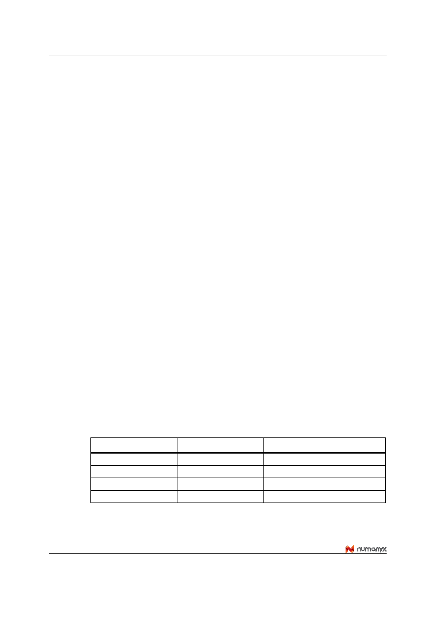
Table 11 shows how to set the X-latency parameter, taking into account the speed class of
the device and the frequency used to read the flash memory in synchronous mode.
Table 11.
X-latency settings
fmax
tKmin
X-latency min
30 MHz
33 ns
2
40 MHz
25 ns
3
54 MHz
19 ns
4
66 MHz
15 ns
4
相关PDF资料 |
PDF描述 |
|---|---|
| M5L28FGNFREQ | CRYSTAL OSCILLATOR, CLOCK, 1.544 MHz - 125 MHz, HCMOS OUTPUT |
| M3L13TCNFREQ | CRYSTAL OSCILLATOR, CLOCK, 1.544 MHz - 125 MHz, HCMOS OUTPUT |
| M3L14FCNFREQ | CRYSTAL OSCILLATOR, CLOCK, 1.544 MHz - 125 MHz, HCMOS OUTPUT |
| M3L15TGNFREQ | CRYSTAL OSCILLATOR, CLOCK, 1.544 MHz - 125 MHz, HCMOS OUTPUT |
| M5L13TCNFREQ | CRYSTAL OSCILLATOR, CLOCK, 1.544 MHz - 125 MHz, HCMOS OUTPUT |
相关代理商/技术参数 |
参数描述 |
|---|---|
| M58WR064T | 制造商:STMICROELECTRONICS 制造商全称:STMicroelectronics 功能描述:64 Mbit (4Mb x 16, Multiple Bank, Burst ) 1.8V Supply Flash Memory |
| M58WR064T100ZB6T | 制造商:STMICROELECTRONICS 制造商全称:STMicroelectronics 功能描述:64 Mbit (4Mb x 16, Multiple Bank, Burst ) 1.8V Supply Flash Memory |
| M58WR064T70ZB6T | 制造商:STMICROELECTRONICS 制造商全称:STMicroelectronics 功能描述:64 Mbit (4Mb x 16, Multiple Bank, Burst ) 1.8V Supply Flash Memory |
| M58WR064T85ZB6T | 制造商:STMICROELECTRONICS 制造商全称:STMicroelectronics 功能描述:64 Mbit (4Mb x 16, Multiple Bank, Burst ) 1.8V Supply Flash Memory |
| M58WR128EB | 制造商:STMICROELECTRONICS 制造商全称:STMicroelectronics 功能描述:128 Mbit 8Mb x 16, Multiple Bank, Burst 1.8V Supply Flash Memory |
发布紧急采购,3分钟左右您将得到回复。