- 您现在的位置:买卖IC网 > PDF目录18765 > MRF89XAT-I/MQ (Microchip Technology)RF ISM BAND TXRX 32 QFN PDF资料下载
参数资料
| 型号: | MRF89XAT-I/MQ |
| 厂商: | Microchip Technology |
| 文件页数: | 69/140页 |
| 文件大小: | 0K |
| 描述: | RF ISM BAND TXRX 32 QFN |
| 标准包装: | 1 |
| 频率: | 863MHz ~ 870MHz,902MHz ~ 928MHz,950MHz ~ 960MHz |
| 数据传输率 - 最大: | 200kbps |
| 调制或协议: | FSK,OOK |
| 应用: | ISM |
| 功率 - 输出: | 12.5dBm |
| 灵敏度: | -113dBm |
| 电源电压: | 2.1 V ~ 3.6 V |
| 电流 - 接收: | 3mA |
| 电流 - 传输: | 25mA |
| 数据接口: | PCB,表面贴装 |
| 存储容量: | * |
| 天线连接器: | PCB,表面贴装 |
| 工作温度: | -40°C ~ 85°C |
| 封装/外壳: | 32-WFQFN 裸露焊盘 |
| 包装: | 标准包装 |
| 其它名称: | MRF89XAT-I/MQDKR |
第1页第2页第3页第4页第5页第6页第7页第8页第9页第10页第11页第12页第13页第14页第15页第16页第17页第18页第19页第20页第21页第22页第23页第24页第25页第26页第27页第28页第29页第30页第31页第32页第33页第34页第35页第36页第37页第38页第39页第40页第41页第42页第43页第44页第45页第46页第47页第48页第49页第50页第51页第52页第53页第54页第55页第56页第57页第58页第59页第60页第61页第62页第63页第64页第65页第66页第67页第68页当前第69页第70页第71页第72页第73页第74页第75页第76页第77页第78页第79页第80页第81页第82页第83页第84页第85页第86页第87页第88页第89页第90页第91页第92页第93页第94页第95页第96页第97页第98页第99页第100页第101页第102页第103页第104页第105页第106页第107页第108页第109页第110页第111页第112页第113页第114页第115页第116页第117页第118页第119页第120页第121页第122页第123页第124页第125页第126页第127页第128页第129页第130页第131页第132页第133页第134页第135页第136页第137页第138页第139页第140页
�� �
�
�MRF89XA�
�3.4.11�
�BIT� SYNCHRONIZER�
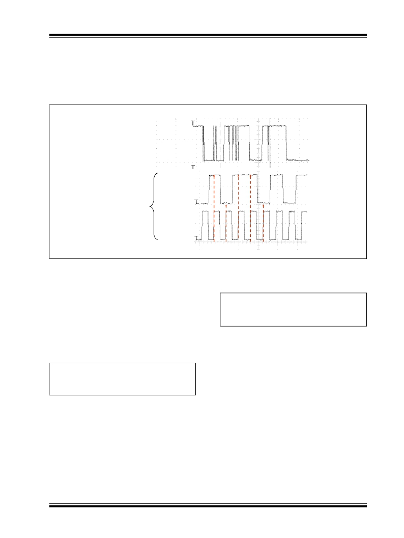
�The� Bit� Synchronizer� (BitSync)� block� provides� a� clean�
�and� synchronized� digital� output� that� is� free� of� glitches.�
�Figure� 3-13� illustrates� the� BitSync� block� output� when� a�
�Raw� Demodulator� FSK� or� OOK� output� is� fed� to� it.�
�FIGURE� 3-13:�
�BitSync� BLOCK� OUTPUT� SIGNALS�
�Raw� demodulator�
�output�
�(FSK� or� OOK)�
�DATA�
�BitSync� Output�
�To� DATA� pin� and�
�DCLK� in�
�Continuous� mode�
�DCLK�
�IRQ1�
�NumberOfBits� =� 1� ---� -----------�
�The� BitSync� can� be� disabled� by� setting� the� BSYNCEN�
�bit� (SYNCREG<6>)� to� ‘� 1� ’� and� by� holding� the� IRQ1� pin�
�(pin� 22)� low.� However,� for� optimum� receiver� perfor-�
�mance,� it� has� to� be� used� when� the� device� is� running� in�
�Continuous� mode.� With� this� option� a� DCLK� signal� is�
�present� on� the� IRQ1� pin.�
�The� BitSync� is� automatically� activated� in� Buffered� and�
�Packet� modes.� The� bit� synchronizer� bit-rate� is� con-�
�trolled� by� the� BRVAL<6:0>� bits� (BRSREG<6:0>).� For� a�
�given� bit� rate,� this� parameter� is� determined� by�
�Equation� 3-16� .�
�EQUATION� 3-16:�
�that� the� BitSync� can� withstand.� It� can� be� esti-�
�mated� as� given� in� Equation� 3-17� .�
�EQUATION� 3-17:�
�?� BR�
�2� Δ� BR�
�This� implies� approximately� six� consecutive� unbalanced�
�bytes� when� the� Bit� Rate� precision� is� 1%,� which� is� easily�
�achievable� (crystal� tolerance� is� or� should� be� at� least� in�
�the� range� of� 50� to� 100� ppm).�
�f� xtal�
�?� [� 1� +� val� (� BRVAL<6:0>� )� ]�
�BR� =� ----------------------------------------------------------------------�
�64�
�3.4.12�
�ALTERNATIVE� SETTINGS� FOR�
�BITSYNC� AND� ACTIVE� FILTER�
�Bit� Synchronizer� and� Active� channel� filter� settings� are�
�For� proper� operation,� the� Bit� Synchronizer� must� first�
�receive� three� bytes� of� alternating� logic� value� preamble,�
�(that� is,� ‘� 0101� ’� sequences).� After� this� start-up� phase,�
�the� rising� edge� of� the� DCLK� signal� is� centered� on� the�
�demodulated� bit.� Subsequent� data� transitions� will�
�preserve� this� centering.� This� has� two� implications:�
�?� If� the� bit� rates� of� Transmitter� and� Receiver� are�
�known� to� be� the� same,� the� MRF89XA� will� be� able�
�to� receive� an� infinite� unbalanced� sequence� (all�
�‘� 0� ’s� or� all� ‘� 1� ’s)� with� no� restriction.�
�?� If� there� is� a� difference� in� bit� rate� between� TX� and�
�RX,� the� amount� of� adjacent� bits� at� the� same� level�
�a� function� of� the� reference� oscillator� crystal� frequency,�
�f� xtal� .� Settings� other� than� those� programmable� with� a�
�12.8� MHz� crystal� can� be� obtained� by� selecting� the� cor-�
�rect� reference� oscillator� frequency.�
�?� 2010–2011� Microchip� Technology� Inc.�
�Preliminary�
�DS70622C-page� 69�
�相关PDF资料 |
PDF描述 |
|---|---|
| 241-5-12L | XFRMR PWR 115V 12.6VCT 1A LEADS |
| DPC-40-250 | XFRMR PWR 115/230V 40VCT 250MA |
| ST-5-56 | XFRMR PWR 115V 28V 440MA 12VA |
| 6221 | TIP STAIN-STEEL SHARP-PT .06"DMM |
| ST-5-48 | XFRMR PWR 115V 24V 500MA 12VA |
相关代理商/技术参数 |
参数描述 |
|---|---|
| MRF8HP21080HR3 | 功能描述:射频MOSFET电源晶体管 HV8 2.1GHZ 160W NI780H-4 RoHS:否 制造商:Freescale Semiconductor 配置:Single 晶体管极性: 频率:1800 MHz to 2000 MHz 增益:27 dB 输出功率:100 W 汲极/源极击穿电压: 漏极连续电流: 闸/源击穿电压: 最大工作温度: 封装 / 箱体:NI-780-4 封装:Tray |
| MRF8HP21080HR5 | 功能描述:射频MOSFET电源晶体管 HV8 2.1GHZ 160W NI780H-4 RoHS:否 制造商:Freescale Semiconductor 配置:Single 晶体管极性: 频率:1800 MHz to 2000 MHz 增益:27 dB 输出功率:100 W 汲极/源极击穿电压: 漏极连续电流: 闸/源击穿电压: 最大工作温度: 封装 / 箱体:NI-780-4 封装:Tray |
| MRF8HP21080HSR3 | 功能描述:射频MOSFET电源晶体管 HV8 2.1GHZ 160W NI780S-4 RoHS:否 制造商:Freescale Semiconductor 配置:Single 晶体管极性: 频率:1800 MHz to 2000 MHz 增益:27 dB 输出功率:100 W 汲极/源极击穿电压: 漏极连续电流: 闸/源击穿电压: 最大工作温度: 封装 / 箱体:NI-780-4 封装:Tray |
| MRF8HP21080HSR5 | 功能描述:射频MOSFET电源晶体管 HV8 2.1GHZ 160W NI780S-4 RoHS:否 制造商:Freescale Semiconductor 配置:Single 晶体管极性: 频率:1800 MHz to 2000 MHz 增益:27 dB 输出功率:100 W 汲极/源极击穿电压: 漏极连续电流: 闸/源击穿电压: 最大工作温度: 封装 / 箱体:NI-780-4 封装:Tray |
| MRF8HP21130HR3 | 功能描述:射频MOSFET电源晶体管 HV8 2.1GHZ 130W NI780-4 RoHS:否 制造商:Freescale Semiconductor 配置:Single 晶体管极性: 频率:1800 MHz to 2000 MHz 增益:27 dB 输出功率:100 W 汲极/源极击穿电压: 漏极连续电流: 闸/源击穿电压: 最大工作温度: 封装 / 箱体:NI-780-4 封装:Tray |
发布紧急采购,3分钟左右您将得到回复。