- 您现在的位置:买卖IC网 > PDF目录229297 > MT46V32M8BG-6AT:G 32M X 8 DDR DRAM, 0.7 ns, PBGA60 PDF资料下载
参数资料
| 型号: | MT46V32M8BG-6AT:G |
| 元件分类: | DRAM |
| 英文描述: | 32M X 8 DDR DRAM, 0.7 ns, PBGA60 |
| 封装: | (8 X 14) MM, LEAD FREE,PLASTIC, FBGA-60 |
| 文件页数: | 33/93页 |
| 文件大小: | 3632K |
第1页第2页第3页第4页第5页第6页第7页第8页第9页第10页第11页第12页第13页第14页第15页第16页第17页第18页第19页第20页第21页第22页第23页第24页第25页第26页第27页第28页第29页第30页第31页第32页当前第33页第34页第35页第36页第37页第38页第39页第40页第41页第42页第43页第44页第45页第46页第47页第48页第49页第50页第51页第52页第53页第54页第55页第56页第57页第58页第59页第60页第61页第62页第63页第64页第65页第66页第67页第68页第69页第70页第71页第72页第73页第74页第75页第76页第77页第78页第79页第80页第81页第82页第83页第84页第85页第86页第87页第88页第89页第90页第91页第92页第93页
PDF: 09005aef80768abb/Source: 09005aef82a95a3a
Micron Technology, Inc., reserves the right to change products or specifications without notice.
DDR_x4x8x16_Core2.fm - 256Mb DDR: Rev. O, Core DDR: Rev. B 1/09 EN
37
2003 Micron Technology, Inc. All rights reserved.
256Mb: x4, x8, x16 DDR SDRAM
Electrical Specifications – DC and AC
30. The input capacitance per pin group will not differ by more than this maximum
amount for any given device.
31. CK and CK# input slew rate must be ≥1V/ns (≥2 V/ns if measured differentially).
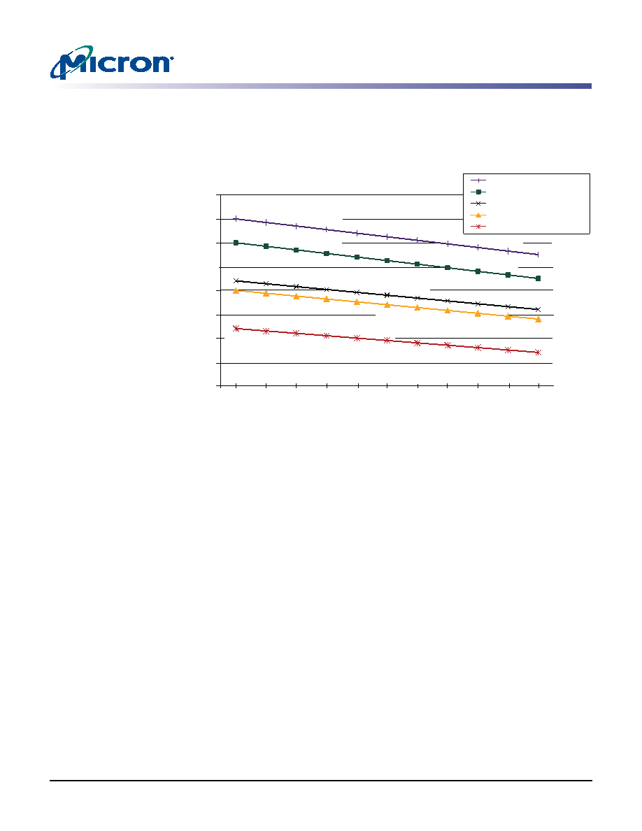
Figure 12:
Derating Data Valid Window (tQH – tDQSQ)
32. DQ and DM input slew rates must not deviate from DQS by more than 10%. If the DQ/
DM/DQS slew rate is less than 0.5 V/ns, timing must be derated: 50ps must be added
to tDS and tDH for each 100 mV/ns reduction in slew rate. For -5B, -6, and
-6T speed grades, the slew rate must be ≥0.5 V/ns. If the slew rate exceeds 4 V/ns,
functionality is uncertain.
33. VDD must not vary more than 4% if CKE is not active while any bank is active.
34. The clock is allowed up to ±150ps of jitter. Each timing parameter is allowed to vary by
the same amount.
35. tHP (MIN) is the lesser of tCL (MIN) and tCH (MIN) actually applied to the device CK
and CK# inputs, collectively, during bank active.
36. READs and WRITEs with auto precharge are not allowed to be issued until tRAS (MIN)
can be satisfied prior to the internal PRECHARGE command being issued.
37. Any positive glitch must be less than 1/3 of the clock cycle and not more than +400mV
or 2.9V (+300mV or 2.9V maximum for -5B), whichever is less. Any negative glitch
must be less than 1/3 of the clock cycle and not exceed either –300mV or 2.2V (2.4V for
-5B), whichever is more positive. The average cannot be below the +2.5V (2.6V for -5B)
minimum.
38. Normal output drive curves:
38a. The full driver pull-down current variation from MIN to MAX process; tempera-
ture and voltage will lie within the outer bounding lines of the V-I curve of
38b. The driver pull-down current variation, within nominal voltage and temperature
limits, is expected, but not guaranteed, to lie within the inner bounding lines of
the V-I curve of Figure 13 on page 38.
3.0ns
2.5ns
2.0ns
1.5ns
1.0ns
50/50
49/51
48/53
46/54
47/53
45/55
-6T @ tCK = 7.5ns
-75E / -75 @ tCK = 7.5ns
-6 @ tCK = 6ns
-6T @ tCK = 6ns
-5B @ tCK = 5ns
1.48
1.45
1.43
1.40
1.38
1.35
2.75
2.60
2.56
2.53
2.45
2.41
2.38
2.68
2.35
2.31
2.28
2.13
2.20
2.16
2.43
2.10
2.07
2.04
1.89
1.86
1.83
1.80
1.98
1.95
2.00
1.97
1.94
1.91
1.88
1.73
1.70
1.82
1.79
1.58
1.55
Clock Duty Cycle
Data
V
a
lid
Window
2.71
2.46
1.53
2.64
2.39
1.92
1.76
1.85
1.60
1.50
2.49
2.50
2.24
2.01
相关PDF资料 |
PDF描述 |
|---|---|
| M29F800FB55N3E2 | 512K X 16 FLASH 5V PROM, 55 ns, PDSO48 |
| MC12L1NZGF | ROTARY SWITCH-12POSITIONS, SP12T, LATCHED, 0.25A, 28VDC, PANEL MOUNT-THREADED |
| MD00S1NCQF | ROTARY SWITCH-6POSITIONS, DP6T, LATCHED, 0.25A, 28VDC, THROUGH HOLE-STRAIGHT |
| MD06L1NZGD | ROTARY SWITCH-6POSITIONS, DP6T, LATCHED, 0.25A, 28VDC, PANEL MOUNT-THREADED |
| MD06L2NCQD | ROTARY SWITCH-6POSITIONS, DP6T, LATCHED, 0.25A, 28VDC, THROUGH HOLE-STRAIGHT |
相关代理商/技术参数 |
参数描述 |
|---|
发布紧急采购,3分钟左右您将得到回复。