- 您现在的位置:买卖IC网 > PDF目录229297 > MT46V32M8BG-6AT:G 32M X 8 DDR DRAM, 0.7 ns, PBGA60 PDF资料下载
参数资料
| 型号: | MT46V32M8BG-6AT:G |
| 元件分类: | DRAM |
| 英文描述: | 32M X 8 DDR DRAM, 0.7 ns, PBGA60 |
| 封装: | (8 X 14) MM, LEAD FREE,PLASTIC, FBGA-60 |
| 文件页数: | 57/93页 |
| 文件大小: | 3632K |
第1页第2页第3页第4页第5页第6页第7页第8页第9页第10页第11页第12页第13页第14页第15页第16页第17页第18页第19页第20页第21页第22页第23页第24页第25页第26页第27页第28页第29页第30页第31页第32页第33页第34页第35页第36页第37页第38页第39页第40页第41页第42页第43页第44页第45页第46页第47页第48页第49页第50页第51页第52页第53页第54页第55页第56页当前第57页第58页第59页第60页第61页第62页第63页第64页第65页第66页第67页第68页第69页第70页第71页第72页第73页第74页第75页第76页第77页第78页第79页第80页第81页第82页第83页第84页第85页第86页第87页第88页第89页第90页第91页第92页第93页
PDF: 09005aef80768abb/Source: 09005aef82a95a3a
Micron Technology, Inc., reserves the right to change products or specifications without notice.
DDR_x4x8x16_Core2.fm - 256Mb DDR: Rev. O, Core DDR: Rev. B 1/09 EN
58
2003 Micron Technology, Inc. All rights reserved.
256Mb: x4, x8, x16 DDR SDRAM
Operations
Operating Mode
The normal operating mode is selected by issuing an LMR command with bits A7–An
each set to zero and bits A0–A6 set to the desired values. A DLL reset is initiated by
issuing an LMR command with bits A7 and A9–An each set to zero, bit A8 set to one, and
bits A0–A6 set to the desired values. Although not required by the Micron device, JEDEC
specifications recommend that an LMR command resetting the DLL should always be
followed by an LMR command selecting normal operating mode.
All other combinations of values for A7–An are reserved for future use and/or test
modes. Test modes and reserved states should not be used, as unknown operation or
incompatibility with future versions may result.
Extended Mode Register
The extended mode register controls functions beyond those controlled by the mode
register; these additional functions are DLL enable/disable and output drive strength.
These functions are controlled via the bits shown in Figure 25 on page 59. The extended
mode register is programmed via the LMR command to the mode register (with BA0 = 1
and BA1 = 0) and will retain the stored information until it is programmed again or until
the device loses power. The enabling of the DLL should always be followed by an LMR
command to the mode register (BA0/BA1 = 0) to reset the DLL. The extended mode
register must be loaded when all banks are idle and no bursts are in progress, and the
controller must wait the specified time before initiating any subsequent operation.
Violating either requirement could result in an unspecified operation.
Output Drive Strength
The normal drive strength for all outputs is specified to be SSTL_2, Class II. The Design
Revision F and K devices support a programmable option for reduced drive. This option
is intended for the support of the lighter load and/or point-to-point environments. The
selection of the reduced drive strength will alter the DQ and DQS pins from SSTL_2,
Class II drive strength to a reduced drive strength, which is approximately 54% of the
SSTL_2, Class II drive strength.
DLL Enable/Disable
When the part is running without the DLL enabled, device functionality may be altered.
The DLL must be enabled for normal operation. DLL enable is required during power-
up initialization and upon returning to normal operation after having disabled the DLL
for the purpose of debug or evaluation (when the device exits self refresh mode, the DLL
is enabled automatically). Anytime the DLL is enabled, 200 clock cycles with CKE HIGH
must occur before a READ command can be issued.
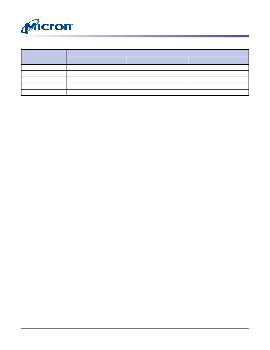
Table 35:
CAS Latency
Speed
Allowable Operating Clock Frequency (MHz)
CL = 2
CL = 2.5
CL = 3
-5B
75
≤ f ≤ 133
75
≤ f ≤ 167
133
≤ f ≤ 200
-6/-6T
75
≤ f ≤ 133
75
≤ f ≤ 167
–
-75E
75
≤ f ≤ 133
75
≤ f ≤ 133
–
-75Z
75
≤ f ≤ 133
75
≤ f ≤ 133
–
-75
75
≤ f ≤ 100
75
≤ f ≤ 133
–
相关PDF资料 |
PDF描述 |
|---|---|
| M29F800FB55N3E2 | 512K X 16 FLASH 5V PROM, 55 ns, PDSO48 |
| MC12L1NZGF | ROTARY SWITCH-12POSITIONS, SP12T, LATCHED, 0.25A, 28VDC, PANEL MOUNT-THREADED |
| MD00S1NCQF | ROTARY SWITCH-6POSITIONS, DP6T, LATCHED, 0.25A, 28VDC, THROUGH HOLE-STRAIGHT |
| MD06L1NZGD | ROTARY SWITCH-6POSITIONS, DP6T, LATCHED, 0.25A, 28VDC, PANEL MOUNT-THREADED |
| MD06L2NCQD | ROTARY SWITCH-6POSITIONS, DP6T, LATCHED, 0.25A, 28VDC, THROUGH HOLE-STRAIGHT |
相关代理商/技术参数 |
参数描述 |
|---|
发布紧急采购,3分钟左右您将得到回复。