- 您现在的位置:买卖IC网 > PDF目录11562 > DS3112+W (Maxim Integrated Products)IC MUX T3/E3 3.3V 256-PBGA PDF资料下载
参数资料
| 型号: | DS3112+W |
| 厂商: | Maxim Integrated Products |
| 文件页数: | 83/133页 |
| 文件大小: | 0K |
| 描述: | IC MUX T3/E3 3.3V 256-PBGA |
| 产品培训模块: | Lead (SnPb) Finish for COTS Obsolescence Mitigation Program |
| 标准包装: | 40 |
| 控制器类型: | 调帧器,多路复用器 |
| 接口: | 并行/串行 |
| 电源电压: | 3.135 V ~ 3.465 V |
| 电流 - 电源: | 150mA |
| 工作温度: | 0°C ~ 70°C |
| 安装类型: | 表面贴装 |
| 封装/外壳: | 256-LBGA |
| 供应商设备封装: | 256-PBGA(27x27) |
| 包装: | 管件 |
第1页第2页第3页第4页第5页第6页第7页第8页第9页第10页第11页第12页第13页第14页第15页第16页第17页第18页第19页第20页第21页第22页第23页第24页第25页第26页第27页第28页第29页第30页第31页第32页第33页第34页第35页第36页第37页第38页第39页第40页第41页第42页第43页第44页第45页第46页第47页第48页第49页第50页第51页第52页第53页第54页第55页第56页第57页第58页第59页第60页第61页第62页第63页第64页第65页第66页第67页第68页第69页第70页第71页第72页第73页第74页第75页第76页第77页第78页第79页第80页第81页第82页当前第83页第84页第85页第86页第87页第88页第89页第90页第91页第92页第93页第94页第95页第96页第97页第98页第99页第100页第101页第102页第103页第104页第105页第106页第107页第108页第109页第110页第111页第112页第113页第114页第115页第116页第117页第118页第119页第120页第121页第122页第123页第124页第125页第126页第127页第128页第129页第130页第131页第132页第133页
DS3112
53 of 133
5.5 T3/E3 Framer Status and Interrupt Register Description
Register Name:
T3E3SR
Register Description:
T3/E3 Status Register
Register Address:
12h
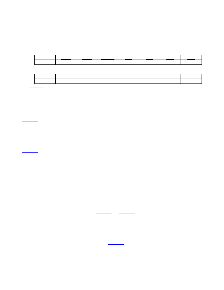
Bit #
7
6
5
4
3
2
1
0
Name
—
RSOF
TSOF
T3IDLE
RAI
AIS
LOF
LOS
Default
—
Bit #
15
14
13
12
11
10
9
8
Name
—
Default
—
Note: See Figure 5-1 for details on the signal flow for the status bits in the T3E3SR register. Bits that are underlined are read-only. All
others are read-write.
Bit 0: Loss Of Signal Occurrence (LOS). This latched read-only alarm-status bit will be set to a one when the T3
or E3 framer detects a loss of signal. This bit will be cleared when read unless a LOS condition still exists. A
change in state of the LOS can cause a hardware interrupt to occur if the LOS bit in the Interrupt Mask for T3E3SR
(IT3E3SR) register is set to a one and the T3E3SR bit in the Interrupt Mask for MSR (IMSR) register is set to a
one. The interrupt will be allowed to clear when this bit is read. The LOS alarm criteria are described in Table 5-1
and Table 5-2.
Bit 1: Loss Of Frame Occurrence (LOF). This latched read-only alarm status bit will be set to a one when the T3
or E3 framer detects a loss of frame. This bit will be cleared when read unless a LOF condition still exists. A
change in state of the LOF can cause a hardware interrupt to occur if the LOF bit in the Interrupt Mask for T3E3SR
(IT3E3SR) register is set to a one and the T3E3SR bit in the Interrupt Mask for MSR (IMSR) register is set to a
one. The interrupt will be allowed to clear when this bit is read. The LOF alarm criteria are described in Table 5-1
and Table 5-2.
Bit 2: Alarm Indication Signal Detected (AIS). This latched read-only alarm-status bit will be set to a one when
the T3 or E3 framer detects an incoming Alarm Indication Signal. This bit will be cleared when read unless an AIS
signal is still present. A change in state of the AIS detection can cause a hardware interrupt to occur if the AIS bit
in the Interrupt Mask for T3E3SR (IT3E3SR) register is set to a one and the T3E3SR bit in the Interrupt Mask for
MSR (IMSR) register is set to a one. The interrupt will be allowed to clear when this bit is read. The AIS alarm
detection criteria is described in Table 5-1 and Table 5-2.
Bit 3: Remote Alarm Indication Detected (RAI). This latched read-only alarm status bit will be set to a one when
the T3 or E3 framer detects an incoming Remote Alarm Indication (RAI) signal. This bit will be cleared when read
unless an RAI signal is still present. A change in state of the RAI detection can cause a hardware interrupt to occur
if the RAI bit in the Interrupt Mask for T3E3SR (IT3E3SR) register is set to a one and the T3E3SR bit in the
Interrupt Mask for MSR (IMSR) register is set to a one. The interrupt will be allowed to clear when this bit is read.
The RAI alarm detection criteria are described in Table 5-1 and Table 5-2. RAI can also be indicated via the FEAC
codes when the device is operated in the C-Bit Parity Mode.
Bit 4: T3 Idle Signal Detected (T3IDLE). This latched read-only alarm status bit will be set to a one when the T3
framer detects an incoming idle signal. This bit will be cleared when read unless the idle signal is still present. A
change in state of idle detection can cause a hardware interrupt to occur if the IDLE bit in the Interrupt Mask for
T3E3SR (IT3E3SR) register is set to a one and the T3E3SR bit in the Interrupt Mask for MSR (IMSR) register is
set to a one. The IDLE detection criteria are described in Table 5-1. The interrupt will be allowed to clear when this
bit is read. When the DS3112 is operated in the E3 mode, this status bit should be ignored.
Bit 5: Transmit T3/E3 Start Of Frame (TSOF). This latched read-only event-status bit will be set to a one on
each T3/E3 transmit frame boundary. This bit is a software version of the FTSOF hardware signal and it will be
cleared when read. The setting of this bit can cause a hardware interrupt to occur if the TSOF bit in the Interrupt
相关PDF资料 |
PDF描述 |
|---|---|
| CONREVSMA007-R58 | CONN RP-SMA MALE END CRIMP RG-58 |
| DS26401NA2+ | IC OCTAL FRAMER T1/E1/J1 256BGA |
| VI-24L-IX-S | CONVERTER MOD DC/DC 28V 75W |
| DS26401+ | IC OCTAL FRAMER T1/E1/J1 256BGA |
| PIC16LF1938-E/SS | MCU 8BIT 16K FLASH 28SSOP |
相关代理商/技术参数 |
参数描述 |
|---|---|
| DS3116MP000 | 制造商:Thomas & Betts 功能描述:MAXGARD - RR8F |
| DS311X | 功能描述:KWIK-CHG DESIGNATION STRIPS DBL RoHS:是 类别:盒,外壳,支架 >> 插线台,插座面板 - 配件 系列:Kwik-Change® 标准包装:50 系列:- 附件类型:模拟插头,双 样式:耳机,0.173" 直径 包括:- |
| DS312 | 功能描述:插线板 DESIGN STRIP COVER RoHS:否 制造商:Switchcraft 产品类型:Bantam (TT) 正规化: 高度/机架数量: 深度: 端接类型: 位置/触点数量:48 |
| DS-312 | 制造商:MA-COM 制造商全称:M/A-COM Technology Solutions, Inc. 功能描述:Four-Way Power Divider, 10 - 500 MHz |
| DS312_09 | 制造商:XILINX 制造商全称:XILINX 功能描述:Spartan-3E FPGA Family: Introduction and Ordering Information |
发布紧急采购,3分钟左右您将得到回复。