- 您现在的位置:买卖IC网 > PDF目录69322 > RK80546KG0802MM (INTEL CORP) 64-BIT, 3000 MHz, MICROPROCESSOR, CPGA604 PDF资料下载
参数资料
| 型号: | RK80546KG0802MM |
| 厂商: | INTEL CORP |
| 元件分类: | 微控制器/微处理器 |
| 英文描述: | 64-BIT, 3000 MHz, MICROPROCESSOR, CPGA604 |
| 封装: | FLIP CHIP, MICRO PGA-604 |
| 文件页数: | 6/106页 |
| 文件大小: | 4724K |
| 代理商: | RK80546KG0802MM |
第1页第2页第3页第4页第5页当前第6页第7页第8页第9页第10页第11页第12页第13页第14页第15页第16页第17页第18页第19页第20页第21页第22页第23页第24页第25页第26页第27页第28页第29页第30页第31页第32页第33页第34页第35页第36页第37页第38页第39页第40页第41页第42页第43页第44页第45页第46页第47页第48页第49页第50页第51页第52页第53页第54页第55页第56页第57页第58页第59页第60页第61页第62页第63页第64页第65页第66页第67页第68页第69页第70页第71页第72页第73页第74页第75页第76页第77页第78页第79页第80页第81页第82页第83页第84页第85页第86页第87页第88页第89页第90页第91页第92页第93页第94页第95页第96页第97页第98页第99页第100页第101页第102页第103页第104页第105页第106页
Datasheet
103
Boxed Processor Specifications
This section describes the cooling requirements of the heatsink solution utilized by the boxed
processor.
8.3.2
Boxed Processor Cooling Requirements
As previously stated the boxed processor will be available in three product configurations. Each
configuration will require unique design considerations. Meeting the processor’s temperature
specifications is also the function of the thermal design of the entire system, and ultimately the
responsibility of the system integrator. The processor temperature specifications are found in
Section 6 of this document.
8.3.2.1
1U Passive CEK Heatsink (1U Form Factor)
In the 1U configuration it is assumed that a chassis duct will be implemented to provide 15 CFM of
airflow to pass through the heatsink fins. The duct should be designed as precisely as possible and
should not allow any air to bypass the heatsink (0” bypass) and a back pressure of 0.38 in. H2O. It
is assumed that a 40
° C T
LA is met. This requires a superior chassis design to limit the TRISE at or
below 5
° C with an external ambient temperature of 35 ° C. Following these guidelines will allow
the designer to meet Thermal Profile B and conform to the thermal requirements of the processor.
8.3.2.2
2U Passive CEK Heatsink (2U and above Form Factor)
Once again a chassis duct is required for the 2U passive heatsink. In this configuration Thermal
Profile A (see Chapter 6) should be followed by supplying 22 CFM of airflow through the fins of
the heatsink with a 0” or no duct bypass and a back pressure of 0.14 in. H2O. The TLA temperature
of 40
° C should be met. This may require the use of superior design techniques to keep T
RISE at or
below 5
° C based on an ambient external temperature of 35 ° C.
8.3.2.3
2U+ Active CEK Thermal Solution (2U+ and above Pedestal)
This thermal solution was designed to help pedestal chassis users to meet the thermal processor
requirements without the use of chassis ducting. It may be necessary to implement some form of
chassis air guide or air duct to meet the TLA temperature of 40 ° C depending on the pedestal
chassis layout. Also, while the active thermal solution is designed to mechanically fit into a 2U
chassis, it may require additional space at the top of the thermal solution to allow sufficient airflow
into the heatsink fan. Therefore, additional design criteria may need to be considered if this thermal
solution is used in a 2U rack mount chassis, or in a chassis that has drive bay obstructions above the
inlet to the fan heatsink.
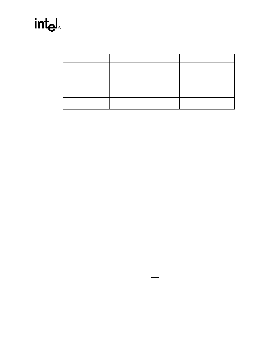
Table 8-4. Fan Cable Connector Supplier and Part Number
Vendor
3-Pin Connector Part Number
4-Pin Connector Part Number
AMP*
Fan Connector: 643815-3
Header: 640456-3
N/A
Walden*
Molex*
Fan Connector: 22-01-3037
Header: 22-23-2031
Fan Connector: 47054-1000
Header: 47053-1000
Wieson*
N/A
Fan Connector: 2510C888-001
Header: 2366C888-007
Foxconn*
N/A
Fan Connector: N/A
Header: HF27040-M1
相关PDF资料 |
PDF描述 |
|---|---|
| RK80546PG0801M | 32-BIT, 3000 MHz, MICROPROCESSOR, CPGA478 |
| RK80546PE0721M | 32-BIT, 2800 MHz, MICROPROCESSOR, CPGA478 |
| RL5C478A | PCI BUS CONTROLLER, PQFP256 |
| RM100355WFQMLV | 100K SERIES, LOW LEVEL TRIGGERED D LATCH, COMPLEMENTARY OUTPUT, CQFP24 |
| RM48L950PGET | 32-BIT, FLASH, 200 MHz, RISC MICROCONTROLLER, PQFP144 |
相关代理商/技术参数 |
参数描述 |
|---|---|
| RK80546KG0802MMS L7ZF | 制造商:Intel 功能描述:MPU Xeon NetBurst 64-Bit 90nm 3GHz 604-Pin FCmPGA4 制造商:Intel 功能描述:XEON 3E GHZ,2M,800MHZ,FC MPGA4 - Trays |
| RK80546KG0881M S L7PF | 制造商:Intel 功能描述:INTEL XEON, 3.2DGHZ,1M,800MHZ,FC-MPGA4 - Trays |
| RK80546KG0882MMS L7ZE | 制造商:Intel 功能描述:XEON 3.2,2M,800MHZ,FC-MPGA4 - Trays |
| RK80546KG1041M | 制造商:Rochester Electronics LLC 功能描述:XEON 3.6GHZ,1M,800MHZ,FC MPGA4 - Bulk |
| RK80546KG1041M S L7PH | 制造商:Intel 功能描述:MPU Xeon 制造商:Intel 功能描述:MPU XEON 90NM 3.6GHZ 604PIN PGA - Trays |
发布紧急采购,3分钟左右您将得到回复。