- 您现在的位置:买卖IC网 > PDF目录98081 > SII3531ACNU PCI BUS CONTROLLER, QCC48 PDF资料下载
参数资料
| 型号: | SII3531ACNU |
| 元件分类: | 总线控制器 |
| 英文描述: | PCI BUS CONTROLLER, QCC48 |
| 封装: | 7 X 7 MM, 0.40 MM PITCH, LEAD FREE, QFN-48 |
| 文件页数: | 63/81页 |
| 文件大小: | 532K |
| 代理商: | SII3531ACNU |
第1页第2页第3页第4页第5页第6页第7页第8页第9页第10页第11页第12页第13页第14页第15页第16页第17页第18页第19页第20页第21页第22页第23页第24页第25页第26页第27页第28页第29页第30页第31页第32页第33页第34页第35页第36页第37页第38页第39页第40页第41页第42页第43页第44页第45页第46页第47页第48页第49页第50页第51页第52页第53页第54页第55页第56页第57页第58页第59页第60页第61页第62页当前第63页第64页第65页第66页第67页第68页第69页第70页第71页第72页第73页第74页第75页第76页第77页第78页第79页第80页第81页
PCI Express to Serial ATA Controller
Data Sheet
Silicon Image, Inc.
2006 Silicon Image, Inc.
SiI-DS-0208-C
66
Bit [18/2]:
Port Ready (W1C).
This bit indicates that the port has become ready to accept and execute
commands. This status indicates that Port Ready (bit 31 in the Port Status register) has made a 0 to 1 transition.
Clearing this status does not change the Port Ready bit in the Port Status register and this status is not set
subsequently until the Port Ready bit changes state.
Bit [17/1]: Command Error (W1C). This bit indicates that an error occurred during command execution. The
error type can be determined via the port error register.
Bit [16/0]:
Command Completion (W1C).
This bit indicates that one or more commands have completed
execution.
6.3.7
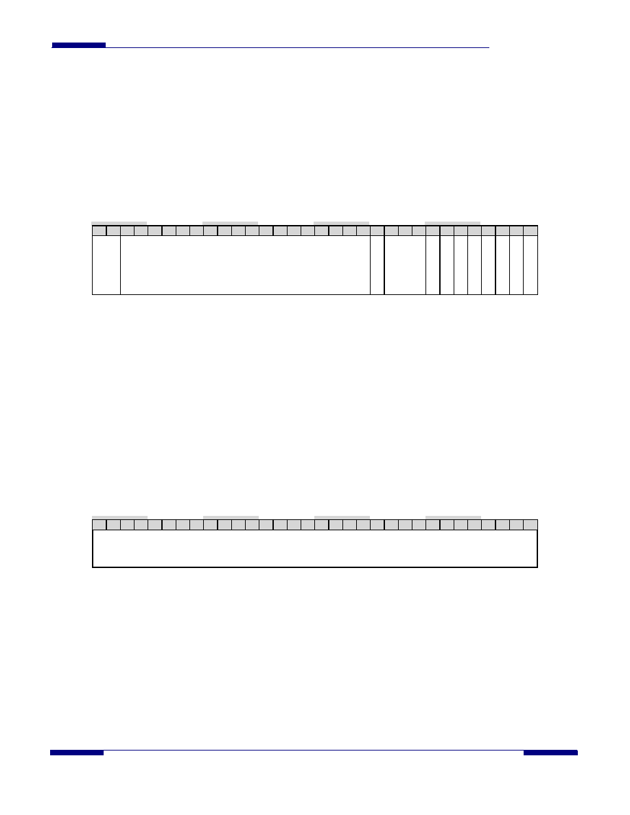
Port Interrupt Enable Set / Port Interrupt Enable Clear
Address Offset: 1010H / 1014H
Access Type: Read/Write 1 Set/Write 1 Clear
Reset Value: 0x0000_0000
31 30 29 28 27 26 25 24 23 22 21 20 19 18 17 16 15 14 13 12 11 10 09 08 07 06 05 04 03 02 01 00
Interrupt
St
eering
Reserved
S
DB
Notify
Reserved
D
evEx
c
hg
U
n
recFIS
C
o
mwake
PhyR
dyC
h
g
PM
Change
Port
R
e
ady
Command
Error
Cmd
Comple
tion
The Interrupt Enable register is controlled by these registers. Writing to the Interrupt Enable Set register sets the Interrupt
Enable bits; the enable bit is set for each corresponding bit to which a 1 is written. Writing to the Interrupt Enable Clear
register clears the Interrupt Enable bits; the enable bit is cleared for each corresponding bit to which a 1 is written. The
Interrupt Enable register may be read at either address offset.
Note that bits 8, 9, and 10 do not have an enable bit; the corresponding interrupts are enabled by corresponding threshold
registers.
Bit [31:30]: Interrupt Steering (R/W). This bit field specifies which one of the four interrupts is to be used for
interrupts from this port. INTA is selected by 00B; INTB by 01B; INTC by 10B; and INTD by 11B.
Bit [29:12,10:8]: Reserved (R). These bits are reserved and return zeros on a read.
Bit [11,7:0]: Interrupt Enables (R/W1S/W1C). These bits are the interrupt enables for the corresponding bits of
the Interrupt Status register.
6.3.8
32-bit Activation Upper Address
Address Offset: 101CH
Access Type: Read/Write
Reset Value: 0x0000_0000
31 30 29 28 27 26 25 24 23 22 21 20 19 18 17 16 15 14 13 12 11 10 09 08 07 06 05 04 03 02 01 00
Upper Address
This register contains the 32-bit value written to the upper half of the Command Activation register when the lower half of that
register is written and the 32-bit Activation control bit (bit 10) is set in the Port Control register.
相关PDF资料 |
PDF描述 |
|---|---|
| SIO10N268-NU | MULTIFUNCTION PERIPHERAL, PQFP128 |
| SIS300 | GRAPHICS PROCESSOR, PBGA365 |
| SK12430PJT | 800 MHz, OTHER CLOCK GENERATOR, PQCC28 |
| SK12439PJ | 800 MHz, OTHER CLOCK GENERATOR, PQCC28 |
| SK12439PJT | 800 MHz, OTHER CLOCK GENERATOR, PQCC28 |
相关代理商/技术参数 |
参数描述 |
|---|---|
| SII3611 | 制造商:SILICONIMAGE 制造商全称:SILICONIMAGE 功能描述:SATALink Device Bridge |
| SII3611CT80-1.5 | 制造商:SILICON IMAGE 功能描述:3611CT80-1.5 |
| SII3723 | 制造商:SILICONIMAGE 制造商全称:SILICONIMAGE 功能描述:Third Generation SATA Port Multiplier Storage Processor |
| SiI3723CNU | 制造商:Silicon Image Inc 功能描述: |
| SII3726 | 制造商:SILICONIMAGE 制造商全称:SILICONIMAGE 功能描述:SATA Port Multiplier |
发布紧急采购,3分钟左右您将得到回复。