- 您现在的位置:买卖IC网 > PDF目录378250 > 865G (Intel Corp.) Intel 865G/865GV Graphics and Memory Controller Hub PDF资料下载
参数资料
| 型号: | 865G |
| 厂商: | Intel Corp. |
| 英文描述: | Intel 865G/865GV Graphics and Memory Controller Hub |
| 中文描述: | 英特尔865G/865GV图形和内存控制器中枢 |
| 文件页数: | 40/249页 |
| 文件大小: | 3540K |
| 代理商: | 865G |
第1页第2页第3页第4页第5页第6页第7页第8页第9页第10页第11页第12页第13页第14页第15页第16页第17页第18页第19页第20页第21页第22页第23页第24页第25页第26页第27页第28页第29页第30页第31页第32页第33页第34页第35页第36页第37页第38页第39页当前第40页第41页第42页第43页第44页第45页第46页第47页第48页第49页第50页第51页第52页第53页第54页第55页第56页第57页第58页第59页第60页第61页第62页第63页第64页第65页第66页第67页第68页第69页第70页第71页第72页第73页第74页第75页第76页第77页第78页第79页第80页第81页第82页第83页第84页第85页第86页第87页第88页第89页第90页第91页第92页第93页第94页第95页第96页第97页第98页第99页第100页第101页第102页第103页第104页第105页第106页第107页第108页第109页第110页第111页第112页第113页第114页第115页第116页第117页第118页第119页第120页第121页第122页第123页第124页第125页第126页第127页第128页第129页第130页第131页第132页第133页第134页第135页第136页第137页第138页第139页第140页第141页第142页第143页第144页第145页第146页第147页第148页第149页第150页第151页第152页第153页第154页第155页第156页第157页第158页第159页第160页第161页第162页第163页第164页第165页第166页第167页第168页第169页第170页第171页第172页第173页第174页第175页第176页第177页第178页第179页第180页第181页第182页第183页第184页第185页第186页第187页第188页第189页第190页第191页第192页第193页第194页第195页第196页第197页第198页第199页第200页第201页第202页第203页第204页第205页第206页第207页第208页第209页第210页第211页第212页第213页第214页第215页第216页第217页第218页第219页第220页第221页第222页第223页第224页第225页第226页第227页第228页第229页第230页第231页第232页第233页第234页第235页第236页第237页第238页第239页第240页第241页第242页第243页第244页第245页第246页第247页第248页第249页
Intel
82865G/82865GV GMCH Datasheet
41
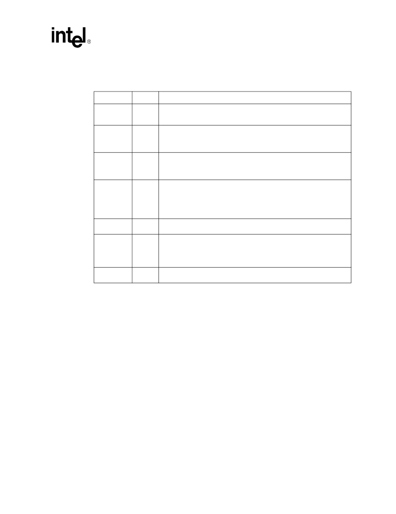
Signal Description
2.7
Clocks, Reset, and Miscellaneous Signals
Signal Name
Type
Description
HCLKP
HCLKN
I
CMOS
Differential Host Clock In:
These pins receive a low voltage differential host
clock from the external clock synthesizer. This clock is used by all of the GMCH
logic that is in the Host clock domain 0.7 V.
GCLKIN
I
LVTTL
66 MHz Clock In:
. This pin receives a 66 MHz clock from the clock synthesizer.
This clock is used by AGP/PCI and HI clock domains.
NOTE:
This clock input is required to be 3.3 V tolerant.
DREFCLK
I
LVTTL
Display Clock Input:
This pin provides a 48 MHz input clock to the Display PLL
that is used for 2D/Video/Flat Panel and DAC.
NOTE:
This clock input is required to be 3.3 V tolerant.
RSTIN#
I
LVTTL
Reset In:
When asserted this signal will asynchronously reset the GMCH logic.
This signal is connected to the PCIRST# output of the ICH5. All AGP/PCI output
and bi-directional signals will also tri-state compliant to PCI Rev 2.0 and 2.1
specifications. This input should have a Schmitt trigger to avoid spurious resets.
NOTE:
This input needs to be 3.3 V tolerant.
PWROK
I
LVTTL
Power OK:
When asserted, PWROK is an indication to the GMCH that the core
power and GCLKIN have been stable for at least 10 μs.
EXTTS#
I
LVTTL
External Thermal Sensor Input
: Open-Drain signal indicating an Over-Temp
condition in the platform. This signal should remains asserted for as long as the
Over-temp Condition exists. This input pin can be programmed to activate
hardware management of memory reads and writes and/or trigger software
interrupts.
TESTIN#
I
Test Input. This signal is used in the GMCH XOR test mode. See
Chapter 8
for
use.
相关PDF资料 |
PDF描述 |
|---|---|
| 8663 | T-1 Subminiature Lamps |
| 8664 | T-1 Subminiature Lamps |
| 8666 | T- Subminiature Lamps |
| 86HF160 | STANDARD RECOVERY DIODES |
| 86HF120M | STANDARD RECOVERY DIODES |
相关代理商/技术参数 |
参数描述 |
|---|---|
| 865G NEO2-LS | 制造商:Micro-Star International 功能描述:865G P4 ATX 800FSB VID - Bulk |
| 865GM2-LS | 制造商:Micro-Star International 功能描述:INTEL P4 800FSB MOTHERBOARD - Bulk |
| 865GV | 制造商:INTEL 制造商全称:Intel Corporation 功能描述:Intel 865G/865GV Graphics and Memory Controller Hub |
| 865GVM3-V | 制造商:Micro-Star International 功能描述:MSI 865GVM3-V MOTHERBOARD - Bulk |
| 865GVM3-V RPL | 制造商:Micro-Star International 功能描述:REPAIR/REPLACEMENT - Bulk |
发布紧急采购,3分钟左右您将得到回复。