- 您现在的位置:买卖IC网 > PDF目录378250 > 865G (Intel Corp.) Intel 865G/865GV Graphics and Memory Controller Hub PDF资料下载
参数资料
| 型号: | 865G |
| 厂商: | Intel Corp. |
| 英文描述: | Intel 865G/865GV Graphics and Memory Controller Hub |
| 中文描述: | 英特尔865G/865GV图形和内存控制器中枢 |
| 文件页数: | 64/249页 |
| 文件大小: | 3540K |
| 代理商: | 865G |
第1页第2页第3页第4页第5页第6页第7页第8页第9页第10页第11页第12页第13页第14页第15页第16页第17页第18页第19页第20页第21页第22页第23页第24页第25页第26页第27页第28页第29页第30页第31页第32页第33页第34页第35页第36页第37页第38页第39页第40页第41页第42页第43页第44页第45页第46页第47页第48页第49页第50页第51页第52页第53页第54页第55页第56页第57页第58页第59页第60页第61页第62页第63页当前第64页第65页第66页第67页第68页第69页第70页第71页第72页第73页第74页第75页第76页第77页第78页第79页第80页第81页第82页第83页第84页第85页第86页第87页第88页第89页第90页第91页第92页第93页第94页第95页第96页第97页第98页第99页第100页第101页第102页第103页第104页第105页第106页第107页第108页第109页第110页第111页第112页第113页第114页第115页第116页第117页第118页第119页第120页第121页第122页第123页第124页第125页第126页第127页第128页第129页第130页第131页第132页第133页第134页第135页第136页第137页第138页第139页第140页第141页第142页第143页第144页第145页第146页第147页第148页第149页第150页第151页第152页第153页第154页第155页第156页第157页第158页第159页第160页第161页第162页第163页第164页第165页第166页第167页第168页第169页第170页第171页第172页第173页第174页第175页第176页第177页第178页第179页第180页第181页第182页第183页第184页第185页第186页第187页第188页第189页第190页第191页第192页第193页第194页第195页第196页第197页第198页第199页第200页第201页第202页第203页第204页第205页第206页第207页第208页第209页第210页第211页第212页第213页第214页第215页第216页第217页第218页第219页第220页第221页第222页第223页第224页第225页第226页第227页第228页第229页第230页第231页第232页第233页第234页第235页第236页第237页第238页第239页第240页第241页第242页第243页第244页第245页第246页第247页第248页第249页
Intel
82865G/82865GV GMCH Datasheet
65
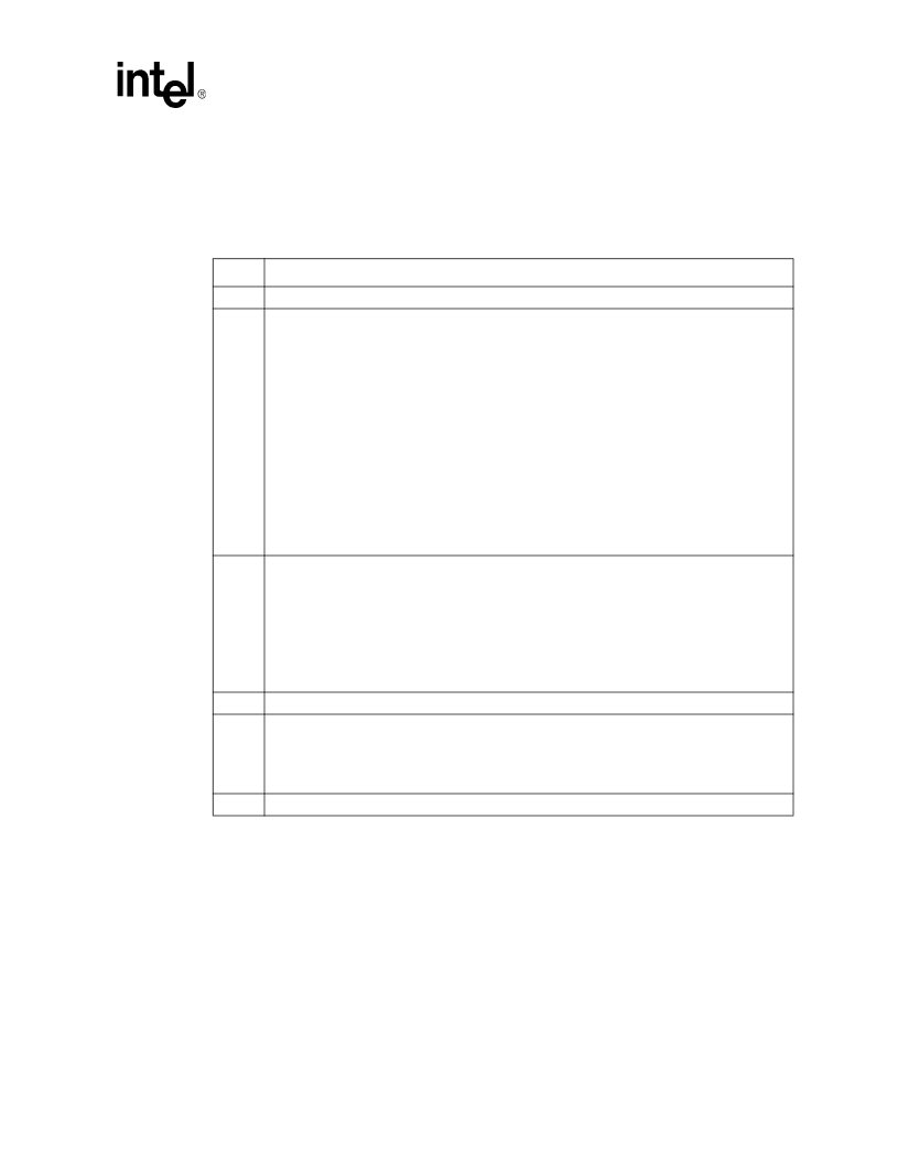
Register Description
3.5.15
GC—Graphics Control Register (Device 0)
Address Offset:
Default Value:
Access:
Size:
52h
0000_1000h
R/W, R/W/L
8 bits
Bit
Descriptions
7
Reserved
6:4
Graphics Mode Select (GMS)—R/W/L.
This field is used to select the amount of main memory that
is pre-allocated to support the Internal Graphics device in VGA (non-linear) and Native (linear)
modes. The BIOS ensures that memory is pre-allocated only when Internal graphics is enabled.
000 = No memory pre-allocated. Device 2 (IGD) does not claim VGA cycles (Memory and I/O), and
the Sub-Class Code field within Device 2 function 0 Class Code register is 80. (Default)
001 = DVMT (UMA) mode:1 MB of memory pre-allocated for frame buffer.
010 = Reserved
011 = DVMT (UMA) mode:8 MB of memory pre-allocated for frame buffer.
100 = DVMT (UMA) mode:16 MB of memory pre-allocated for frame buffer.
101 =Reserved
110 = Reserved
111 = Reserved
NOTE:
These register bits are locked and becomes Read Only when the D_LCK bit in the SMRAM
register is set.
3
Integrated Graphics Disable (IGDIS)—R/W.
0 = IGD Enable. When this bit is 0, the GMCH's Device 1 is disabled such that all configuration
cycles to Device 1 flow through to HI. Also, the Next_Pointer field in the CAPREG register (Dev
0, Offset E4h) will be RO at A0h.
1 = IGD is disabled and AGP Graphics is enabled (default). The GMCH's Device 2 and associated
spaces are disabled; all configuration cycles to Device 2 flow through to HI.
NOTE:
When writing a new value to this bit, software must perform a clock synchronization
sequence.
2
Reserved
1
IGD VGA Disable (IVD)—R/W.
0 = IGD claims VGA memory and I/O cycles; the Sub-Class Code within Device 2 Class Code
register is 00h. (Default)
1 = IGD does not claim VGA cycles (Memory and I/O); the Sub-Class Code field within Device 2
Class Code register is 80h.
0
Reserved
相关PDF资料 |
PDF描述 |
|---|---|
| 8663 | T-1 Subminiature Lamps |
| 8664 | T-1 Subminiature Lamps |
| 8666 | T- Subminiature Lamps |
| 86HF160 | STANDARD RECOVERY DIODES |
| 86HF120M | STANDARD RECOVERY DIODES |
相关代理商/技术参数 |
参数描述 |
|---|---|
| 865G NEO2-LS | 制造商:Micro-Star International 功能描述:865G P4 ATX 800FSB VID - Bulk |
| 865GM2-LS | 制造商:Micro-Star International 功能描述:INTEL P4 800FSB MOTHERBOARD - Bulk |
| 865GV | 制造商:INTEL 制造商全称:Intel Corporation 功能描述:Intel 865G/865GV Graphics and Memory Controller Hub |
| 865GVM3-V | 制造商:Micro-Star International 功能描述:MSI 865GVM3-V MOTHERBOARD - Bulk |
| 865GVM3-V RPL | 制造商:Micro-Star International 功能描述:REPAIR/REPLACEMENT - Bulk |
发布紧急采购,3分钟左右您将得到回复。