- 您现在的位置:买卖IC网 > PDF目录171235 > DSRT-L030-011 (CONEXANT SYSTEMS) SPECIALTY CONSUMER CIRCUIT, XMA PDF资料下载
参数资料
| 型号: | DSRT-L030-011 |
| 厂商: | CONEXANT SYSTEMS |
| 元件分类: | 消费家电 |
| 英文描述: | SPECIALTY CONSUMER CIRCUIT, XMA |
| 文件页数: | 68/86页 |
| 文件大小: | 667K |
| 代理商: | DSRT-L030-011 |
第1页第2页第3页第4页第5页第6页第7页第8页第9页第10页第11页第12页第13页第14页第15页第16页第17页第18页第19页第20页第21页第22页第23页第24页第25页第26页第27页第28页第29页第30页第31页第32页第33页第34页第35页第36页第37页第38页第39页第40页第41页第42页第43页第44页第45页第46页第47页第48页第49页第50页第51页第52页第53页第54页第55页第56页第57页第58页第59页第60页第61页第62页第63页第64页第65页第66页第67页当前第68页第69页第70页第71页第72页第73页第74页第75页第76页第77页第78页第79页第80页第81页第82页第83页第84页第85页第86页
RipTide PCI Audio/Comm Device Family Product Description
70
ROCKWELL PROPRIETARY INFORMATION
1167
shielding. Experience has shown different PC brands can have quite different EMI characteristics of their own. See
Section 18.2.
2.
Surround noisy signals, especially clocks, with a guard-band of thick traces of ground. Pay special attention to where the
guard-bands are grounded, as the effectiveness of this technique will be greatly diminished with the increased physical
distance.
3.
When vias must be used on traces with power/ground distribution, use multiple vias rather than a single via. The more
vias, the lower the impedance.
4.
Avoid vias on traces carrying fast signals at any cost. Every place the impedance on a trace changes an additional EMI
is generated. RipTide device signals are designed to route to the PCI connector and codec without signal crossover.
Therefore, there should be very little need for vias. PCI signals on the blank side of the board should have only one via.
Other PCI signals should have no vias. See Section 18.2.
5.
If radiated emissions move 6 or more dBuV just by slightly moving connected cables, the grounding technique used in
design should be improved. At this point, maximize dumping EMI energy directly to the bracket ground without dumping
too much EMI energy to scattered ground traces on the board.
18.1.4
Filtering
1.
A general rule of thumb is to filter every connector on the board. On audio combo boards, these filters take the form of
ferrite beads and capacitors. Place a ferrite in series with the signal and a capacitor between the signal and ground. After
the signal is filtered, it must not be exposed to any board noise. Therefore, the filter must be as close to the connector as
possible and filtered signals kept away from the digital ground and power.
2.
On some designs, place a ferrite between bracket ground and digital ground. This helps keep digital noise away from the
connector but has the harmful side effect of making the digital area of the board noisier.
18.1.5
Decoupling
1.
Another way to deal with EMI is to short it to ground through proper decoupling capacitors (caps). Because traces and
component leads become inductors at high frequencies, use surface mount caps if possible, and place them close to the
device being decoupled. Decouple power pins of a device directly to associated ground pins of the device between
traces as close to the device as possible, i.e., not to a remote ground plane. If you have power and ground planes,
connect capacitors to the planes with more than one via. This will decrease the lead inductance and increase the
effectiveness of the capacitors.
2.
Capacitors are useful in reducing EMI is that they provide a high frequency short to ground. This is good if the ground
plane is properly grounded (i.e., short path to chassis ground.), However if the ground plane isn’t properly grounded, then
the decoupling caps need to be used to source as much noise to the ground plane as it can handle. Also note that the
desired value of the decoupling cap depends on the frequency that you want to eliminate. With higher system clock rates
it is necessary to have a mixture of values for decoupling caps (e.g., 0.001 uF, 0.01 uF and 0.1 uF).
3.
Sourcing too much energy to ground can be just as harmful EMI-wise as not sourcing enough should the path to ground
be poor. The capacitor value chosen for the offending frequency can be mathematically correct but also cause excessive
EMI ripple on the ground. Unless the impedance of ground traces can be reduced, the solution is to reduce the capacitor
value. As an example, if the board is excessively radiating at 100 MHz with a 0.01 uF cap, try a 0.047. The idea is to only
source as much energy to ground as the ground can handle, no more or it will radiate.
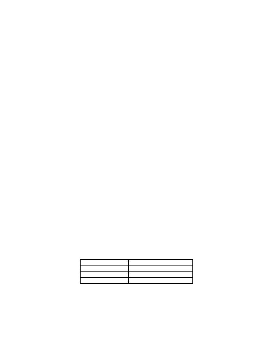
Capacitor Value
Frequency of Reduced EMI
0.1 uF
10 MHz
0.01 uF
30 MHz
0.001 uF
100 MHz
4.
There is some overlap, as these values will change as inductance of the board comes into effect, and the fact you rarely
have just one frequency to contend with. Another rule of thumb, derived from experiences, is 0.1 uF for <80 MHz, 0.01
uF for 60-500 MHz, and 0.001 uF for >400 MHz. The designer should provide several different values for de-coupling
capacitors. These should be spread evenly around the power pins of devices on the board. A few capacitors can be
placed in open areas of the board to stabilize the power and ground.
相关PDF资料 |
PDF描述 |
|---|---|
| DSRT-L050-011 | SPECIALTY CONSUMER CIRCUIT, XMA |
| DSS710D223S12-22 | 1 FUNCTIONS, 12 V, 7 A, DATA LINE FILTER |
| DST9HB32E101Q55J | 1 FUNCTIONS, 250 V, 6 A, DATA LINE FILTER |
| DST9HB32E220Q55J | 1 FUNCTIONS, 250 V, 6 A, DATA LINE FILTER |
| DST9HB32E222Q55J | 1 FUNCTIONS, 250 V, 6 A, DATA LINE FILTER |
相关代理商/技术参数 |
参数描述 |
|---|---|
| DSR-TSS-S1 | 制造商:DOMINANT 制造商全称:DOMINANT Semiconductors 功能描述:Right Angle LED |
| DSR-TSS-S2 | 制造商:DOMINANT 制造商全称:DOMINANT Semiconductors 功能描述:Right Angle LED |
| DSR-TSS-ST2-1 | 制造商:DOMINANT 制造商全称:DOMINANT Semiconductors 功能描述:Right Angle LED |
| DSR-TSS-T1 | 制造商:DOMINANT 制造商全称:DOMINANT Semiconductors 功能描述:Right Angle LED |
| DSR-TSS-T2 | 制造商:DOMINANT 制造商全称:DOMINANT Semiconductors 功能描述:Right Angle LED |
发布紧急采购,3分钟左右您将得到回复。