- 您现在的位置:买卖IC网 > PDF目录11720 > PI7C8154BNAE (Pericom)IC PCI-PCI BRIDGE ASYNC 304-PBGA PDF资料下载
参数资料
| 型号: | PI7C8154BNAE |
| 厂商: | Pericom |
| 文件页数: | 42/114页 |
| 文件大小: | 0K |
| 描述: | IC PCI-PCI BRIDGE ASYNC 304-PBGA |
| 标准包装: | 27 |
| 系列: | * |
| 应用: | * |
| 接口: | * |
| 电源电压: | * |
| 封装/外壳: | 304-BBGA |
| 供应商设备封装: | 304-PBGA(31x31) |
| 包装: | 管件 |
| 安装类型: | 表面贴装 |
第1页第2页第3页第4页第5页第6页第7页第8页第9页第10页第11页第12页第13页第14页第15页第16页第17页第18页第19页第20页第21页第22页第23页第24页第25页第26页第27页第28页第29页第30页第31页第32页第33页第34页第35页第36页第37页第38页第39页第40页第41页当前第42页第43页第44页第45页第46页第47页第48页第49页第50页第51页第52页第53页第54页第55页第56页第57页第58页第59页第60页第61页第62页第63页第64页第65页第66页第67页第68页第69页第70页第71页第72页第73页第74页第75页第76页第77页第78页第79页第80页第81页第82页第83页第84页第85页第86页第87页第88页第89页第90页第91页第92页第93页第94页第95页第96页第97页第98页第99页第100页第101页第102页第103页第104页第105页第106页第107页第108页第109页第110页第111页第112页第113页第114页
PI7C8154B
ASYNCHRONOUS 2-PORT
PCI-to-PCI BRIDGE
Advance Information
Page 33 of 112
JUNE 2008 REVISION 1.1
The lowest two address bits on P_AD[1:0] are 01b.
The bus number in address field P_AD[23:16] is equal to the value in the secondary bus
number register in configuration space.
The bus command on P_CBE[3:0] is a configuration read or configuration write transaction.
When PI7C8154B translates the Type 1 transaction to a Type 0 transaction on the secondary
interface, it performs the following translations to the address:
Sets the lowest two address bits on S_AD[1:0] to 0.
Decodes the device number and drives the bit pattern specified in Table 2-6 on S_AD[31:16]
for the purpose of asserting the device’s IDSEL signal.
Sets S_AD[15:11] to 0.
Leaves unchanged the function number and register number fields.
PI7C8154B asserts a unique address line based on the device number. These address lines may be
used as secondary bus IDSEL signals. The mapping of the address lines depends on the device
number in the Type 1 address bits P_AD[15:11]. Table 2-6 presents the mapping that PI7C8154B
uses.
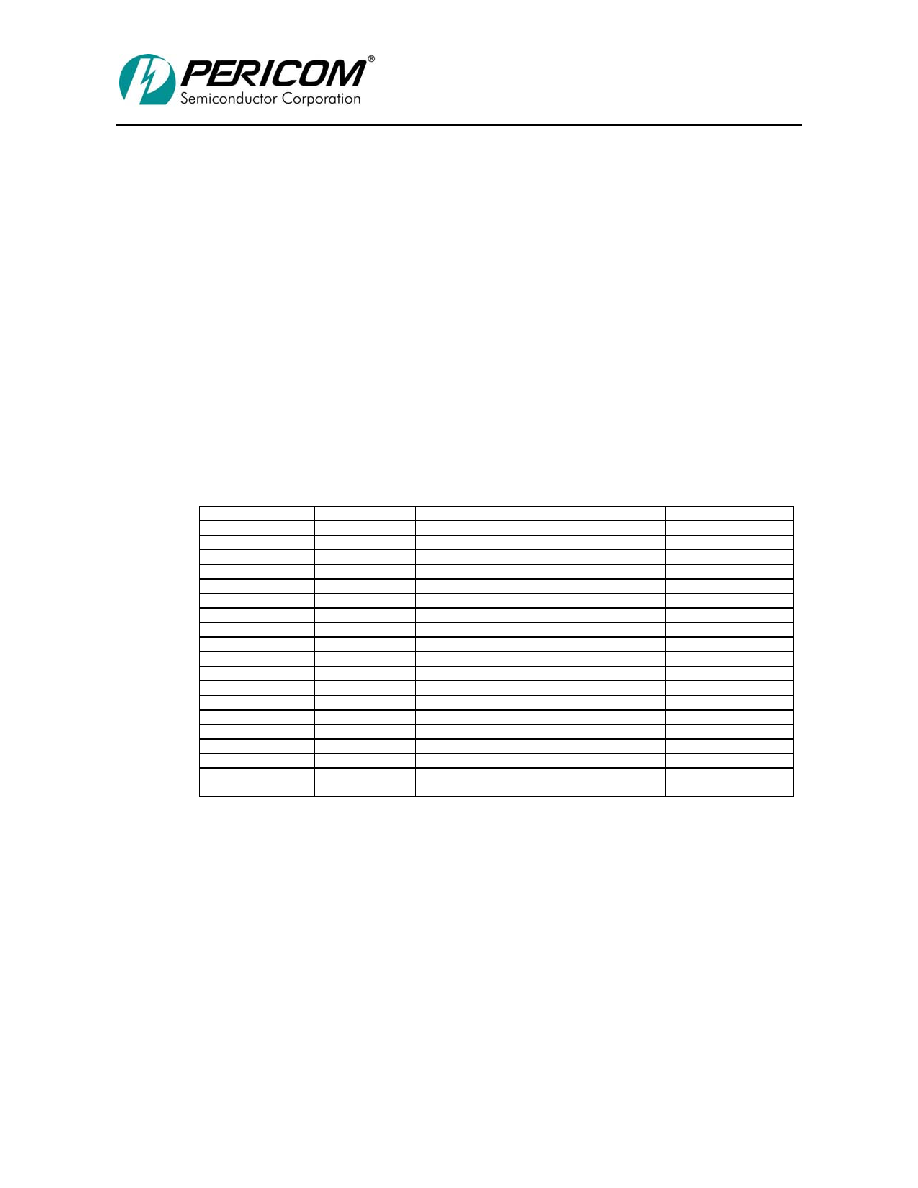
Table 2-6 DEVICE NUMBER TO IDSEL S_AD PIN MAPPING
Device Number
P_AD[15:11]
Secondary IDSEL S_AD[31:16]
S_AD
0h
00000
0000 0000 0000 0001
16
1h
00001
0000 0000 0000 0010
17
2h
00010
0000 0000 0000 0100
18
3h
00011
0000 0000 0000 1000
19
4h
00100
0000 0000 0001 0000
20
5h
00101
0000 0000 0010 0000
21
6h
00110
0000 0000 0100 0000
22
7h
00111
0000 0000 1000 0000
23
8h
01000
0000 0001 0000 0000
24
9h
01001
0000 0010 0000 0000
25
Ah
01010
0000 0100 0000 0000
26
Bh
01011
0000 1000 0000 0000
27
Ch
01100
0001 0000 0000 0000
28
Dh
01101
0010 0000 0000 0000
29
Eh
01110
0100 0000 0000 0000
30
Fh
01111
1000 0000 0000 0000
31
10h – 1Eh
10000 – 11110
0000 0000 0000 0000
-
1Fh
11111
Generate special cycle (P_AD[7:2] = 00h)
0000 0000 0000 0000 (P_AD[7:2] = 00h)
-
PI7C8154B can assert up to 16 unique address lines to be used as IDSEL signals for up to 16
devices on the secondary bus, for device numbers ranging from 0 through 8. Because of electrical
loading constraints of the PCI bus, more than 16 IDSEL signals should not be necessary. However,
if device numbers greater than 16 are desired, some external method of generating IDSEL lines
must be used, and no upper address bits are then asserted. The configuration transaction is still
translated and passed from the primary bus to the secondary bus. If no IDSEL pin is asserted to a
secondary device, the transaction ends in a master abort.
PI7C8154B forwards Type 1 to Type 0 configuration read or write transactions as delayed
transactions. Type 1 to Type 0 configuration read or write transactions are limited to a single 32-bit
data transfer.
相关PDF资料 |
PDF描述 |
|---|---|
| ADM1025AARQ | IC MONITOR SYS/VOLT 5CH 16QSOP |
| ADUC832BCPZ | IC MCU 62K FLASH ADC/DAC 56LFCSP |
| 31-10 | BNC FRONT MOUNT RECEPT |
| D38999/20JD97SN | CONN RCPT 12POS WALL MNT W/SCKT |
| ADUC848BSZ62-5 | IC FLASH MCU W/16BIT ADC 52MQFP |
相关代理商/技术参数 |
参数描述 |
|---|---|
| PI7C8154BNAE-80 | 功能描述:外围驱动器与原件 - PCI 64B/66MHz 2 Port PCI Bridge RoHS:否 制造商:PLX Technology 工作电源电压: 最大工作温度: 安装风格:SMD/SMT 封装 / 箱体:FCBGA-1156 封装:Tray |
| PI7C8154BNAI | 制造商:Pericom Semiconductor Corporation 功能描述: |
| PI7C8154BNAIE | 功能描述:外围驱动器与原件 - PCI 64B/66MHz 2 Port PCI Bridge RoHS:否 制造商:PLX Technology 工作电源电压: 最大工作温度: 安装风格:SMD/SMT 封装 / 箱体:FCBGA-1156 封装:Tray |
| PI7C8154EVB | 功能描述:界面开发工具 64B/66MHz 2 Port PCI Bridge Eval Brd RoHS:否 制造商:Bourns 产品:Evaluation Boards 类型:RS-485 工具用于评估:ADM3485E 接口类型:RS-485 工作电源电压:3.3 V |
| PI7C8154NA-33 | 制造商:PERICOM 功能描述: |
发布紧急采购,3分钟左右您将得到回复。