- 您现在的位置:买卖IC网 > PDF目录11720 > PI7C8154BNAE (Pericom)IC PCI-PCI BRIDGE ASYNC 304-PBGA PDF资料下载
参数资料
| 型号: | PI7C8154BNAE |
| 厂商: | Pericom |
| 文件页数: | 69/114页 |
| 文件大小: | 0K |
| 描述: | IC PCI-PCI BRIDGE ASYNC 304-PBGA |
| 标准包装: | 27 |
| 系列: | * |
| 应用: | * |
| 接口: | * |
| 电源电压: | * |
| 封装/外壳: | 304-BBGA |
| 供应商设备封装: | 304-PBGA(31x31) |
| 包装: | 管件 |
| 安装类型: | 表面贴装 |
第1页第2页第3页第4页第5页第6页第7页第8页第9页第10页第11页第12页第13页第14页第15页第16页第17页第18页第19页第20页第21页第22页第23页第24页第25页第26页第27页第28页第29页第30页第31页第32页第33页第34页第35页第36页第37页第38页第39页第40页第41页第42页第43页第44页第45页第46页第47页第48页第49页第50页第51页第52页第53页第54页第55页第56页第57页第58页第59页第60页第61页第62页第63页第64页第65页第66页第67页第68页当前第69页第70页第71页第72页第73页第74页第75页第76页第77页第78页第79页第80页第81页第82页第83页第84页第85页第86页第87页第88页第89页第90页第91页第92页第93页第94页第95页第96页第97页第98页第99页第100页第101页第102页第103页第104页第105页第106页第107页第108页第109页第110页第111页第112页第113页第114页
PI7C8154B
ASYNCHRONOUS 2-PORT
PCI-to-PCI BRIDGE
Advance Information
Page 58 of 114
JUNE 2008 REVISION 1.1
Bridge sets the data parity detected bit in the status register, if the parity error response bit is
set in the command register of the primary interface.
Bridge asserts P_SERR# and sets the signaled system error bit in the status register, if all the
following conditions are met:
The SERR# enable bit is set in the command register
The parity error response bit is set in the bridge control register of the secondary interface
The parity error response bit is set in the command register of the primary interface
Bridge has not detected the parity error on the secondary (initiator) bus, which the parity
error is not forwarded from the secondary bus to the primary bus
Assertion of P_SERR# is used to signal the parity error condition when the initiator does not know
that the error occurred. Because the data has already been delivered with no errors, there is no other
way to signal this information back to the initiator. If the parity error has forwarded from the
initiating bus to the target bus, P_SERR# will not be asserted.
5.3
DATA PARITY ERROR REPORTING
In the previous sections, the responses of the bridge to data parity errors are presented according to
the type of transaction in progress. This section organizes the responses of the bridge to data parity
errors according to the status bits that the bridge sets and the signals that it asserts.
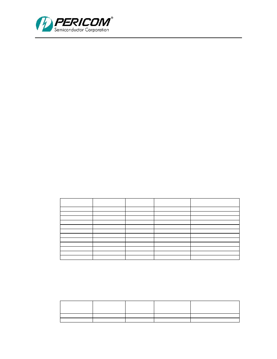
Table 5-1 shows setting the detected parity error bit in the status register, corresponding to the
primary interface. This bit is set when PI7C8154B detects a parity error on the primary interface.
Table 5-1 SETTING THE PRIMARY INTERFACE DETECTED PARITY ERROR BIT
(bit 31 of offset 04h)
Primary Detected
Parity Error Bit
Transaction Type
Direction
Bus Where Error
Was Detected
Primary/ Secondary Parity
Error Response Bits
0
Read
Downstream
Primary
x / x
0
Read
Downstream
Secondary
x / x
1
Read
Upstream
Primary
x / x
0
Read
Upstream
Secondary
x / x
1
Posted Write
Downstream
Primary
x / x
0
Posted Write
Downstream
Secondary
x / x
0
Posted Write
Upstream
Primary
x / x
0
Posted Write
Upstream
Secondary
x / x
1
Delayed Write
Downstream
Primary
x / x
0
Delayed Write
Downstream
Secondary
x / x
0
Delayed Write
Upstream
Primary
x / x
0
Delayed Write
Upstream
Secondary
x / x
Note: x=don’t care
Table 5-2 shows setting the detected parity error bit in the secondary status register, corresponding
to the secondary interface. This bit is set when PI7C8154B detects a parity error on the secondary
interface.
Table 5-2 SETTING THE SECONDARY INTERFACE DETECTED PARITY ERROR BIT
Secondary
Detected Parity
Error Bit
Transaction Type
Direction
Bus Where Error
Was Detected
Primary/ Secondary Parity
Error Response Bits
0
Read
Downstream
Primary
x / x
1
Read
Downstream
Secondary
x / x
相关PDF资料 |
PDF描述 |
|---|---|
| ADM1025AARQ | IC MONITOR SYS/VOLT 5CH 16QSOP |
| ADUC832BCPZ | IC MCU 62K FLASH ADC/DAC 56LFCSP |
| 31-10 | BNC FRONT MOUNT RECEPT |
| D38999/20JD97SN | CONN RCPT 12POS WALL MNT W/SCKT |
| ADUC848BSZ62-5 | IC FLASH MCU W/16BIT ADC 52MQFP |
相关代理商/技术参数 |
参数描述 |
|---|---|
| PI7C8154BNAE-80 | 功能描述:外围驱动器与原件 - PCI 64B/66MHz 2 Port PCI Bridge RoHS:否 制造商:PLX Technology 工作电源电压: 最大工作温度: 安装风格:SMD/SMT 封装 / 箱体:FCBGA-1156 封装:Tray |
| PI7C8154BNAI | 制造商:Pericom Semiconductor Corporation 功能描述: |
| PI7C8154BNAIE | 功能描述:外围驱动器与原件 - PCI 64B/66MHz 2 Port PCI Bridge RoHS:否 制造商:PLX Technology 工作电源电压: 最大工作温度: 安装风格:SMD/SMT 封装 / 箱体:FCBGA-1156 封装:Tray |
| PI7C8154EVB | 功能描述:界面开发工具 64B/66MHz 2 Port PCI Bridge Eval Brd RoHS:否 制造商:Bourns 产品:Evaluation Boards 类型:RS-485 工具用于评估:ADM3485E 接口类型:RS-485 工作电源电压:3.3 V |
| PI7C8154NA-33 | 制造商:PERICOM 功能描述: |
发布紧急采购,3分钟左右您将得到回复。