- 您现在的位置:买卖IC网 > PDF目录85254 > SPMC16V1CPU20 (MOTOROLA INC) 16-BIT, MROM, 20.97 MHz, MICROCONTROLLER, PQFP100 PDF资料下载
参数资料
| 型号: | SPMC16V1CPU20 |
| 厂商: | MOTOROLA INC |
| 元件分类: | 微控制器/微处理器 |
| 英文描述: | 16-BIT, MROM, 20.97 MHz, MICROCONTROLLER, PQFP100 |
| 封装: | TQFP-100 |
| 文件页数: | 4/128页 |
| 文件大小: | 571K |
| 代理商: | SPMC16V1CPU20 |
第1页第2页第3页当前第4页第5页第6页第7页第8页第9页第10页第11页第12页第13页第14页第15页第16页第17页第18页第19页第20页第21页第22页第23页第24页第25页第26页第27页第28页第29页第30页第31页第32页第33页第34页第35页第36页第37页第38页第39页第40页第41页第42页第43页第44页第45页第46页第47页第48页第49页第50页第51页第52页第53页第54页第55页第56页第57页第58页第59页第60页第61页第62页第63页第64页第65页第66页第67页第68页第69页第70页第71页第72页第73页第74页第75页第76页第77页第78页第79页第80页第81页第82页第83页第84页第85页第86页第87页第88页第89页第90页第91页第92页第93页第94页第95页第96页第97页第98页第99页第100页第101页第102页第103页第104页第105页第106页第107页第108页第109页第110页第111页第112页第113页第114页第115页第116页第117页第118页第119页第120页第121页第122页第123页第124页第125页第126页第127页第128页
MC68HC16V1
MOTOROLA
MC68HC16V1TS/D
101
5.5.1 QSPI Pins
Seven pins are associated with the QSPI. When not needed for a QSPI function, they can be configured
as general-purpose I/O pins. The PCS0/SS pin can function as a peripheral chip-select output, slave
select input, or general-purpose I/O. Refer to Table 54 for QSPI input and output pins and their func-
tions.
5.5.2 QSPI Registers
The programming model for the QSPI submodule consists of the QSM global and pin control registers,
four QSPI control registers, one status register, and the 80-byte QSPI RAM.
The CPU can read and write to registers and RAM. The four control registers must be initialized before
the QSPI is enabled to ensure defined operation. SPCR1 should be written last because it contains
QSPI enable bit SPE. Asserting this bit starts the QSPI. The QSPI control registers are reset to a de-
fined state and can then be changed by the CPU. Reset values are shown below each register.
Table 55 shows a memory map of the QSPI.
Writing a different value into any control register except SPCR2 while the QSPI is enabled disrupts op-
eration. SPCR2 is buffered to prevent disruption of the current serial transfer. After completion of the
current serial transfer, the new SPCR2 values become effective.
Writing the same value into any control register except SPCR2 while the QSPI is enabled has no effect
on QSPI operation. Rewriting NEWQP[3:0] in SPCR2 causes execution to restart at the designated lo-
cation.
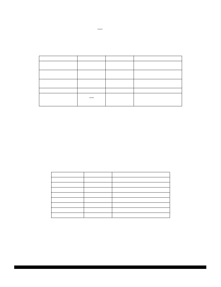
Table 54 QSPI Pins
Pin Name(s)
Mnemonic(s)
Mode
Function
Master In Slave Out
MISO
Master
Slave
Serial Data Input to QSPI
Serial Data Output from QSPI
Master Out Slave In
MOSI
Master
Slave
Serial Data Output from QSPI
Serial Data Input to QSPI
Serial Clock
SCK
Master
Slave
Clock Output from QSPI
Clock Input to QSPI
Peripheral Chip Selects
PCS[3:1]
Master
Select Peripherals
Peripheral Chip Select
Slave Select
PCS0
SS
Master
Slave
Selects Peripheral
Causes mode fault
Initiates Serial Transfer
Table 55 QSPI Memory Map
Address
Name
Usage
$YFFC18
SPCR0
QSPI Control Register 0
$YFFC1A
SPCR1
QSPI Control Register 1
$YFFC1C
SPCR2
QSPI Control Register 2
$YFFC1E
SPCR3
QSPI Control Register 3
$YFFC1F
SPSR
QSPI Status Register
$YFFD00
RR[0:F]
QSPI Receive Data (16 Words)
$YFFD20
TR[0:F]
QSPI Transmit Data (16 Words)
$YFFD40
CR[0:F]
QSPI Command Control (8 Words)
相关PDF资料 |
PDF描述 |
|---|---|
| S1C60N05F0A0100 | MICROCONTROLLER, PQFP60 |
| SC3S12P128J0CLHR | 16-BIT, MROM, 1.05 MHz, MICROCONTROLLER, PQFP64 |
| SC3S12P128J0CLH | 16-BIT, MROM, 1.05 MHz, MICROCONTROLLER, PQFP64 |
| SC3S12P128J0CQKR | 16-BIT, MROM, 1.05 MHz, MICROCONTROLLER, PQFP80 |
| S908QY2AD1MDW | 8-BIT, FLASH, 8 MHz, MICROCONTROLLER, PDSO16 |
相关代理商/技术参数 |
参数描述 |
|---|---|
| SPMC387-01 | 制造商:SSDI 制造商全称:Solid States Devices, Inc 功能描述:50 WATT RADIATION HARDENED DC-DC POWER CONVERTER |
| SPMC68CK338CPV14 | 制造商:FREESCALE 制造商全称:Freescale Semiconductor, Inc 功能描述:32-Bit Modular Microcontroller |
| SPMC802B | 制造商:未知厂家 制造商全称:未知厂家 功能描述:32-pin General Purpose Microcontroller (OTP) |
| SPMC802B-C | 制造商:未知厂家 制造商全称:未知厂家 功能描述:32-pin General Purpose Microcontroller (OTP) |
| SPMC802B-PD03 | 制造商:未知厂家 制造商全称:未知厂家 功能描述:32-pin General Purpose Microcontroller (OTP) |
发布紧急采购,3分钟左右您将得到回复。